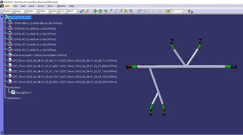
Wiring harness design in CATIA V5 - 3D modeling Week 4 Challenge
SOFTWARE USED :
- CATIA V5
STEPS TO DEFINE GIVEN HARNESS LAYOUT :
- First, download above mentioned connector 3D data from www.te.com
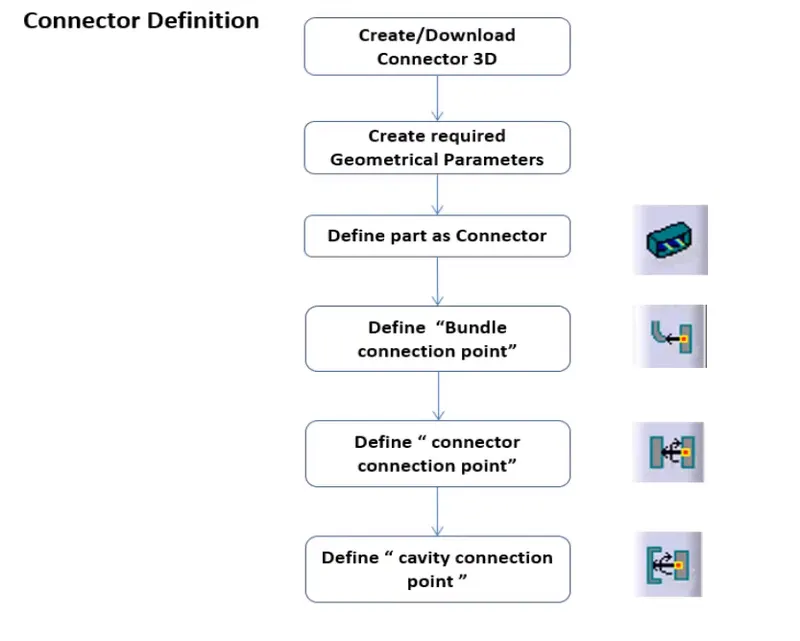
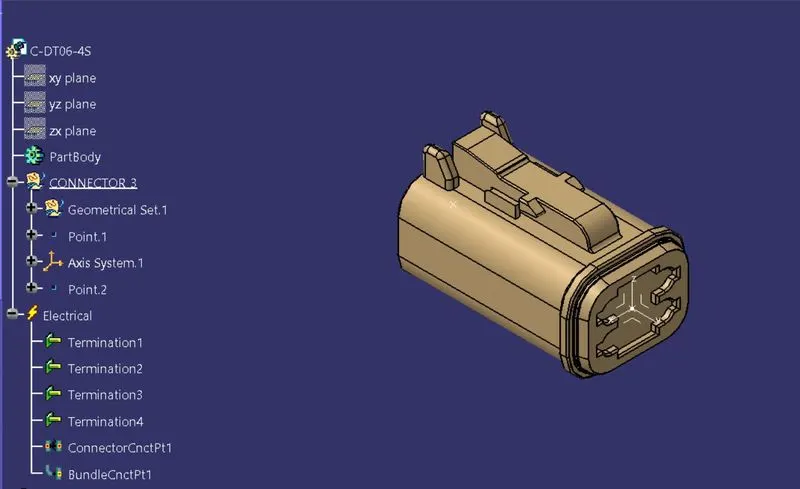
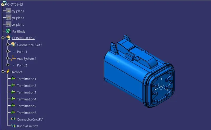
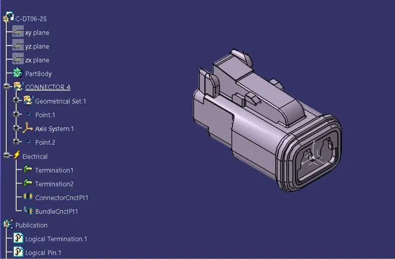
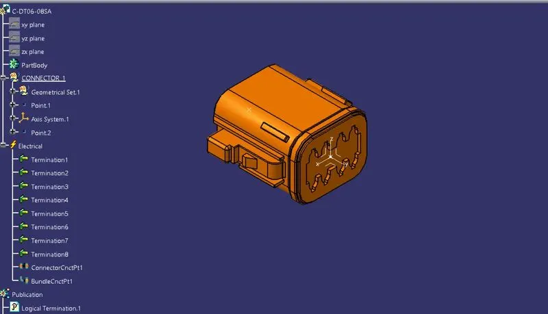
- Create necessary points and axis system on connectors and define them as electrical connector by using mentioned steps in below image.
- DT06-4S
- DT06-6S
- DT06-2S
- DT06-08SA
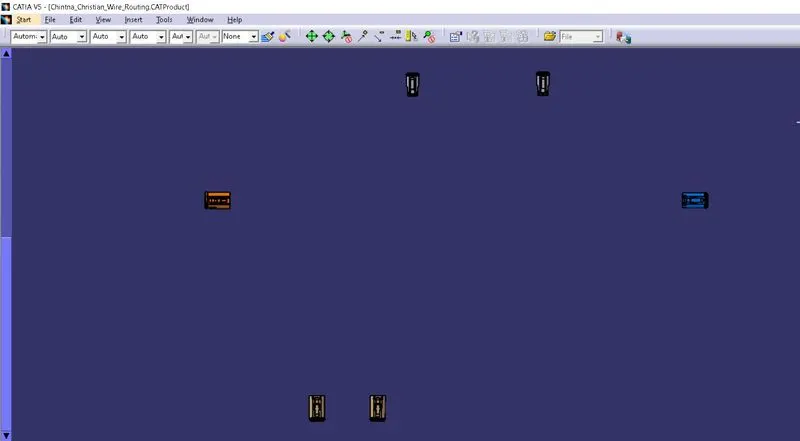
Position all connectors in CATIA Assembly according to Harness Layout image by using MANIPULATION option or COMPASS.
Now, go to ‘ELECTRICAL HARNESS ASSEMBLY’ workbench and define given product file as electrical assembly by using GEOMETRICAL BUNDLE option.
Create Multi-Branches between connectors by defining route definition with outer diameter and inner diameter as shown in below image.
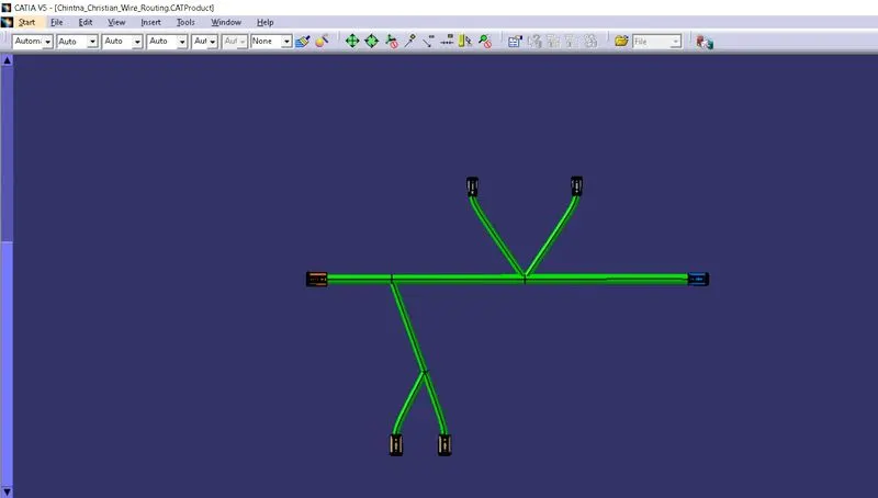
In last stage, create a protective covering from Corrugated Tubes catalogue. In this way, wiring harness with protective covering is defined.