Wiring harness design in CATIA V5 - 3D modeling Week 4 Challenge
| WIRING HARNESS ROUTING |
AIM:
The main objectives are,
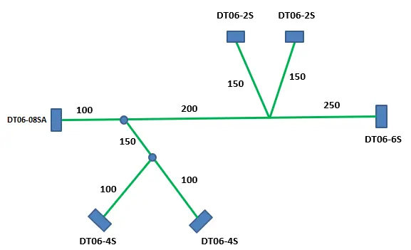
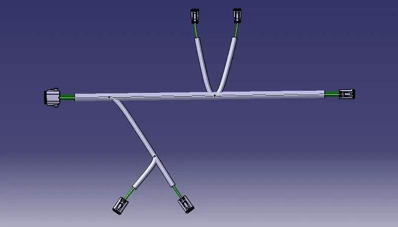
1.To Route the following harness layout in Electrical workbench.
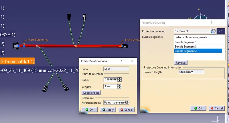
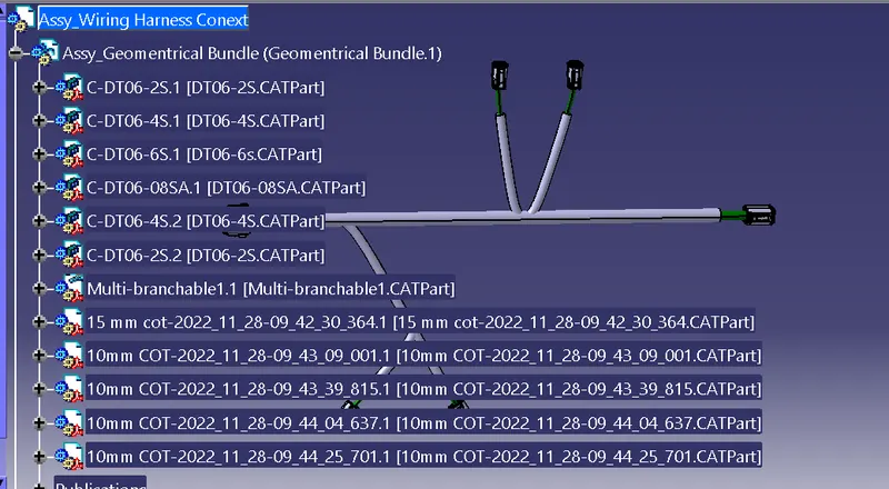
2. To Add protective covering on all branches connected to DT06-2S & DT06-4S connectors. Keep end extremity at 30mm (from connectors end)
|
INPUTS |
|
DT06-4S |
|
DT06-6S |
|
DT06-2S |
| DT06-08SA |
INTRODUCTION:
WIRING HARNESS
A wire harness, often referred to as a cable harness or wiring assembly, is a systematic and integrated arrangement of cables within an insulated material. The purpose of the assembly is to transmit signal or electrical power. Cables are bound together with straps, cable ties, cable lacing, sleeves, electrical tape, conduit, or a combination thereof. The wire harness simplifies the connection to larger components by integrating the wiring into a single unit for “drop-in” installation.
PROTECTIVE COVERING
It's developed to protect the wiring bundles which are used in routing. As a protection cover which ensures safety of bundle from sharp edges, high temperature, dust and water. It can be selected by different factors such surrounding parts and environment. Moreover, It will be selected by either cotton or polymer and pvc.
corrugated tubes,Convolutes, Sleeves and many other types of coverings are used to protect the wiring harness.
CONNECTOR
Connectors are the electro-mechanical devices used to form a continuous electronic signal to connect wire harnesses to a power source or circuit. On a basic level, connectors consist of male-ended plugs and female-ended jacks that can be joined together to relay an electronic signal. They are the familiar mating pair of polarized multi-pin connectors with wire leads. A male-ended plastic housing with release fits into a snap-mounted female-ended chassis mounting. The pair can be connected or disconnected easily and come in a variety of sizes, shapes, materials, quality, and dimensions—circular, header, pin, crimped, multitap—which are dependent on the application.
PROCEDURES:
1. Defining the given part as an Electrical Component _
Steps to be followed are,
|
1. Create 3D object/Get from vendor |
| 2. Define Geomentrical parameters |
| 3. Define the 3d object as a connector |
|
4. Define connection points |
Creation of geomentrical parameters such as points and Coordinatinf system,
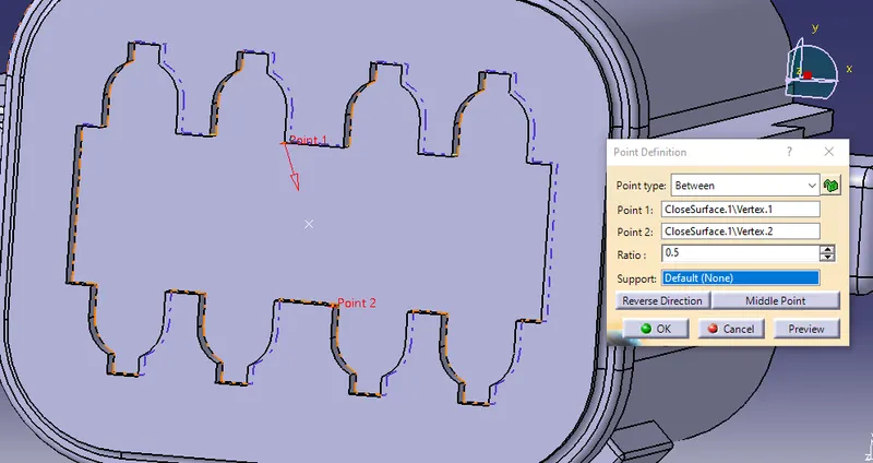
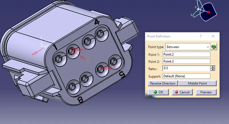
Above image shows pont creating on other side of connector to create bundle connection point.
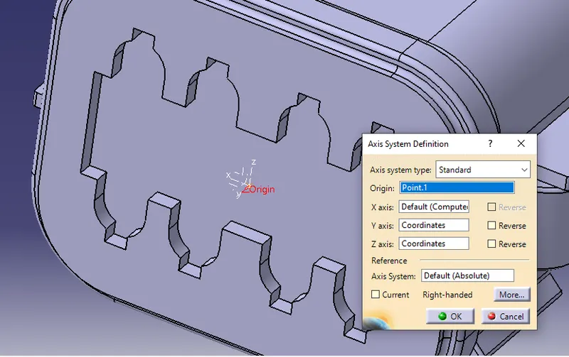
conditions - Y axis should be in the mating direction
x axis should be in the locking mechanism direction
z axis should be in the direction towards top surface
Defining the connector to create connection points,
To create connection points we should have a electrical equipment like connectors, we should define the part or 3d object as an electrical device.
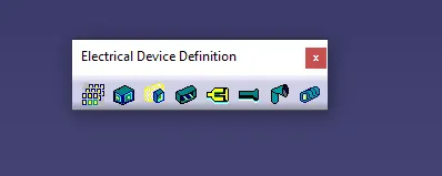 ->Definition toolbar to define the given object as electrical
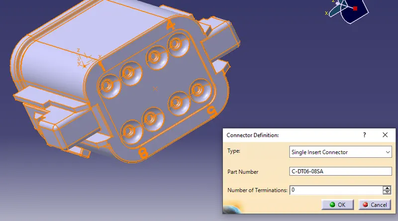
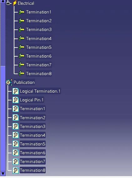
The above image shows The properties of electrical Device.
Electical Connection Point defenition Toolbar
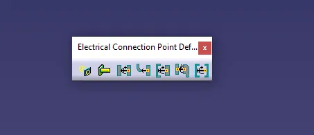 -> this is the toolbar in electrical part design to define connecting points.
Bundle Connection point
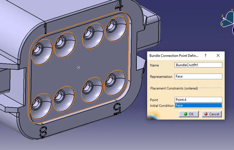
This is the point where bundle segment or wire point end when get routed to a connector. This point is known as Bundle Connection Point. At the time of defining bundle connection point, the number of terminals and a face is also provided as an input data.
Connector Connection point:
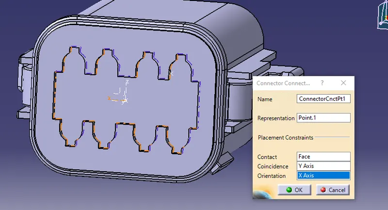
A connection point is a point in an electrical connector where a cable begins or ends. Electrical connectors are required to have at least one connection point with the route type set to Electrical. This defines the part as an electrical connector and provides information about the route
This point also used to make an assembly with other systems. This willl be defined by geomentrical parameters that we have already created.
- In Connector connection axis system, we have to always ensure that y-axis should be alwyas in the direction of mating axis of all the connectors.
- And x-axis should be in the diretion of locking mechanism and z-axis should be left-right side of the connector according to the orientation.
2. Harness Assembly_
| The Harness Context Assembly |
| Geomentrical Bundle |
| Electrical Bundle |
The harness context assembly:
This is the top_level product file that contains the harness geometrical bundle/assembly and the wire harness electrical bundle.
Geomentrical Bundle:
This sublevel product file is the wire harness product that contains all of the harness components i.e clips , supports, Connectors, splices,annotations and actual physical bunsle segments and branches.
Electriacl Bundle:
This sub level product file contains all of the electrical circuit information.
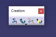 -> Toolbar to Define geomentrical bundle
After Defining Harness context, the sub level product should be defined as geomentrical bundle for further operation.
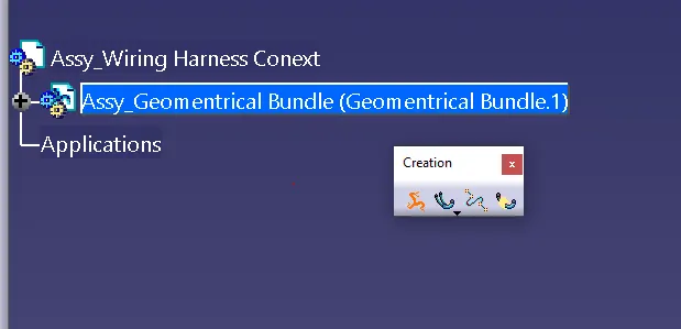
All the necessary parts such as connectors, clamps are inserted for routing.
Note_ All the parts shoud be Electrically Defined
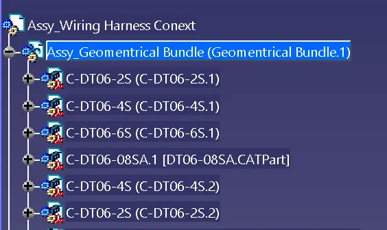
All the components should be positioned at desired locations.
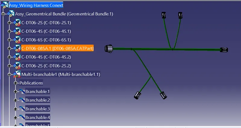
Multi_Branching:
-> toolbar for multi branching
Bundles are developed between two electrical components by using bundle definition point.
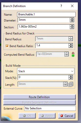
The above image shows creation of bundle.
Bend radius_used to specify flexilibility of bundle. The radius should be minimum of 1.4 times of the bundle Diameter.
Build mode_ used to give extra length The place where the extra lengths are needed.
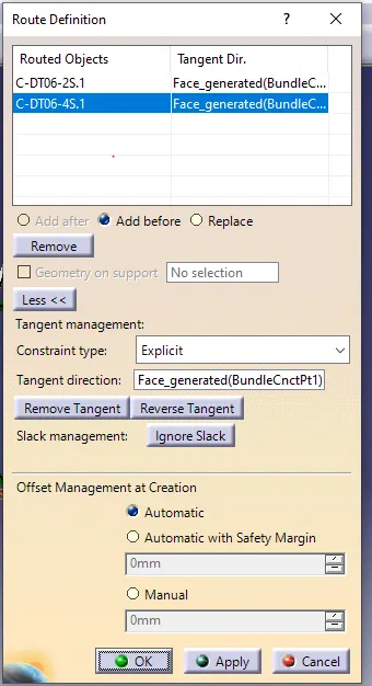
The above images shows, slecetion of connectors.
Tangent Management_ to create tangents on bundle based on connector ends.
Offset management_ used to specify the values for clearence between surface or along the surface.
mostly used in external reference toavoid fauling of bundle with support plate.
3.PROTECTIVE COVERING
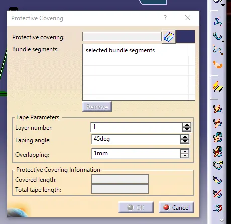
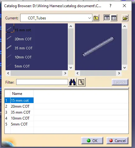
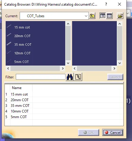
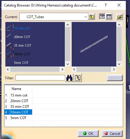
COT_tubes are used here to protect the bundles, which are stored in catalog.
Main Branching:
RESULT:
CONCLUSION,
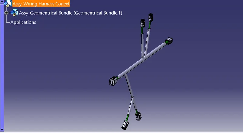
Thus All the given components are defined succesfully as an Electrical Component by using Electrical workbench and routed Harness assymbly layout. Moreover, Protective covers are added for all connectors with an end extrimity of 30mm from connectors end.