Wiring harness design in CATIA V5 - 3D modeling Week 4 Challenge
AIM:
-
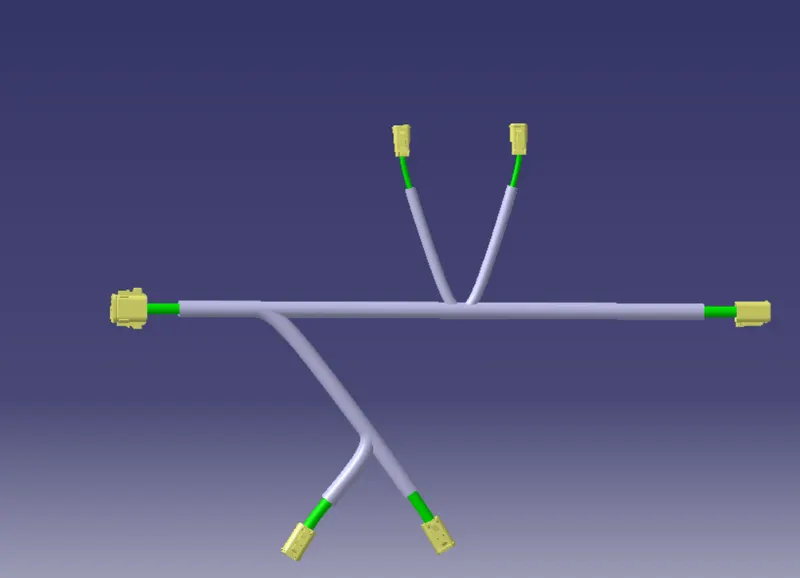
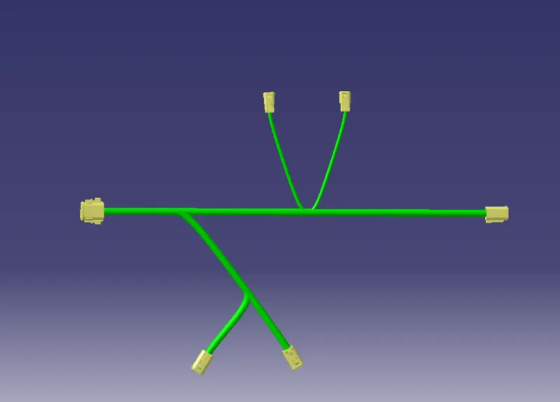
Route the following harness layout in Electrical workbench. Make assumption for harness bundle diameters. Use Following connectors as shown in layout diagram.
Add protective covering on all branches connected to DT06-2S & DT06-4S connectors. Keep end extremity at 30mm (from connectors end).
STAGES TO ATTAIN THE WIRING HARNESS ASSEMBLY:
1.MECHANICAL PART- ELECTRICAL PART DESIGN:
- The given mechanical parts to be convert into electrical component with its properties.
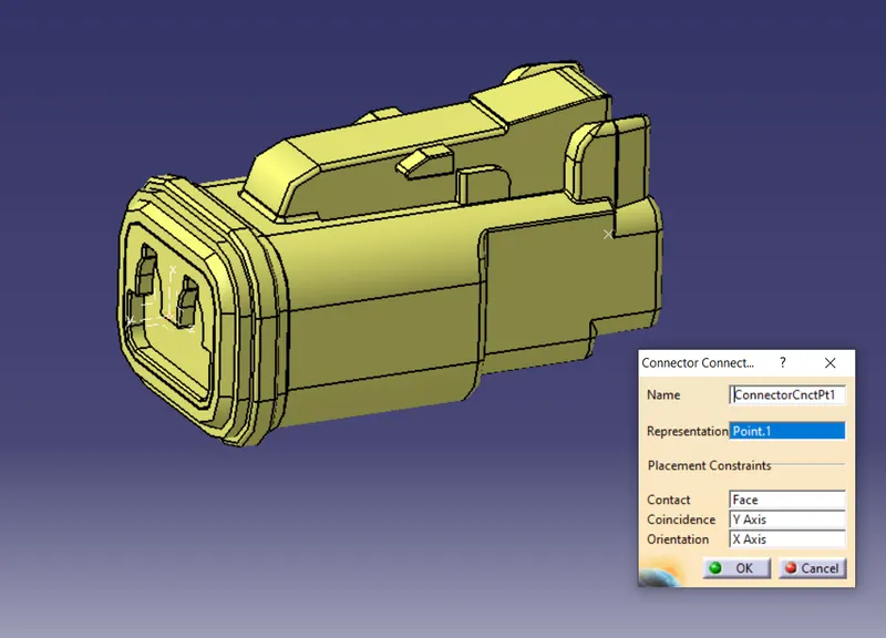
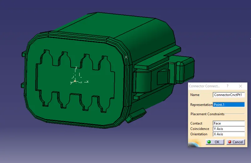
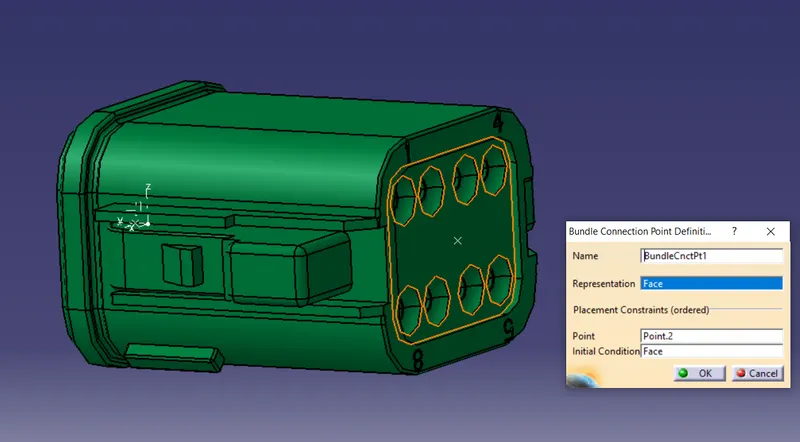
- At the first, setting the certain required geometical parameters to given mechanical part such as, Connector connection point, Bundle entry point and axis system for the connectors to be inserted in the part design work bench.
- After setting these geometrical parameters navigate into the electrical part design workbench.
- Define the part as electrical connector component using the electrical device definition and define points as connector connection point and bundle entry point.
1.2 Pole connector- DT06-2S Connector:
Connector connection point:
Bundle entry connection point:
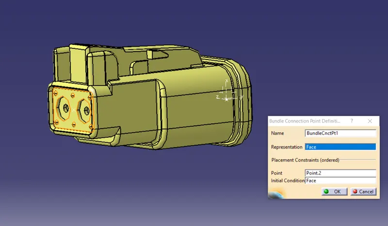
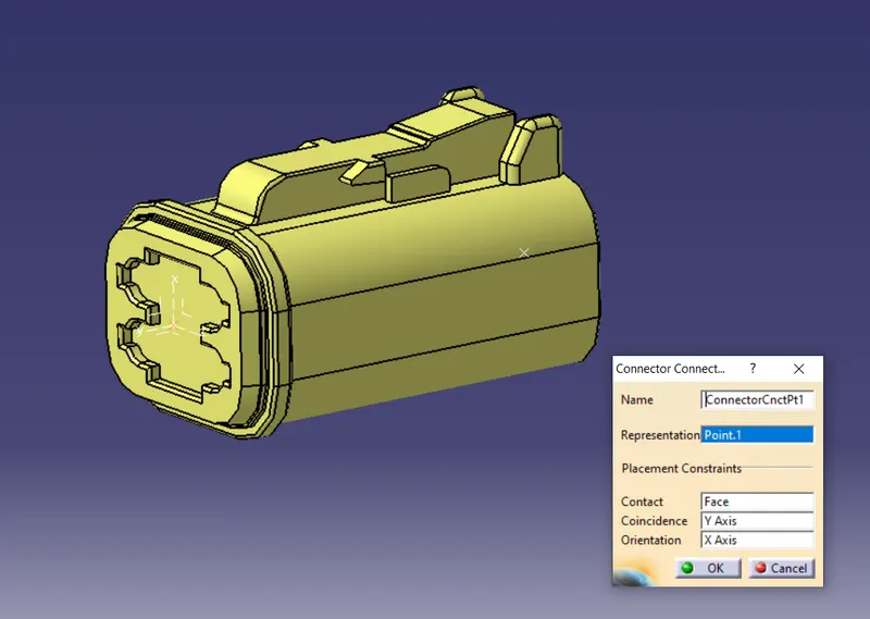
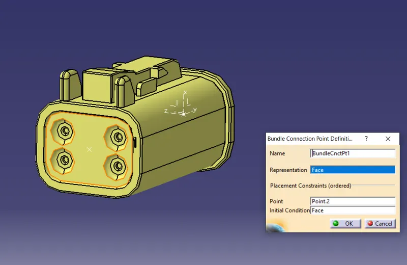
2.4 Pole connector-DT06-4S Connector:
Connector connectioin point:
Bundle entry connection point:
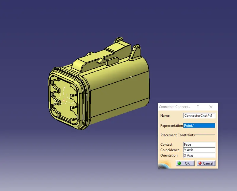
3.6 Pole connector-DT06-6S Connector:
Connector connection point:
Bundle entry connection point: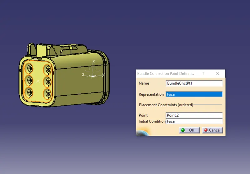
4.8 Pole connector-DT06-8S Connector:
Connector connection point:
Bundle entry connection point:
2.WIRING HARNESS ASSEMBLY WORK BENCH:
- Insert the electrical components into the product. Locate the connectors at the particular position in same plane for routing the wiring harness bundle to connector.
- Click the multi branchable document in wiring harness assembly tool bar.Then its automatically navigate into the wiring harness installation work bench. Apply the branch definition tool for routing the wiring harness bundle to connector with branches.
- To create the sub branch from main branch,Apply the add branch point tool to main branch then the main branch is split into two bundle segments.
- Routing the wiring harness bundle to the lateral connector with reference of one splitted bundle and connector.
- After routing the wiring harnes bundle to all connectors, Apply the cot tubes as a protection covering component with extreme end of 30 mm gap between the connector.
PRODUCT IMAGES OF WIRING HARNESS ASSEMBLY