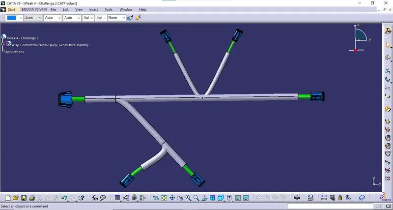
Wiring harness design in CATIA V5 - 3D modeling Week 4 Challenge
COMPONENTS USED:
1. DT06-08SA
i. Download 3D Part: The 3D model is downloaded from the given link and saved as a Catpart file.
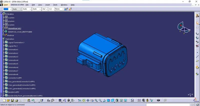
ii. Geometrical Parameters:
* Bundle Entry Point: The bundle entry Point is created at the rear part of the connector.
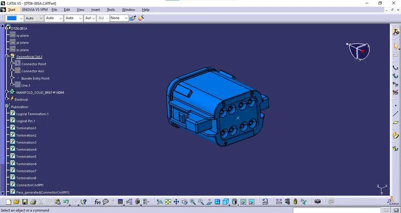
* Connector Point: The connector Point is created at the mating side of the connector.
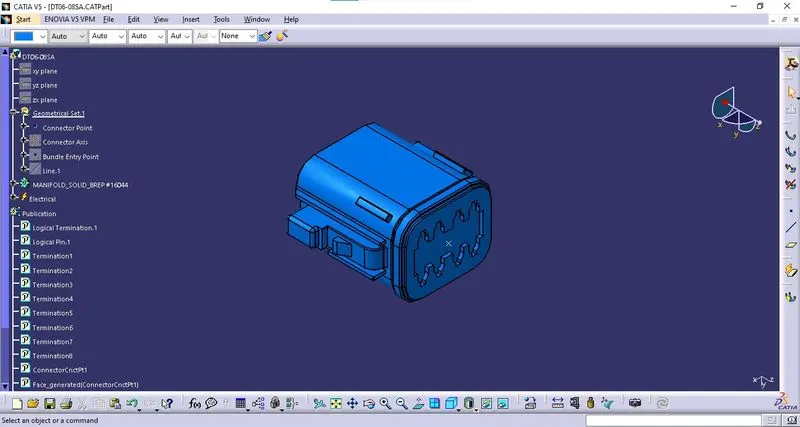
* Connector Axis: The connector axis is created with respect to Connector Point.
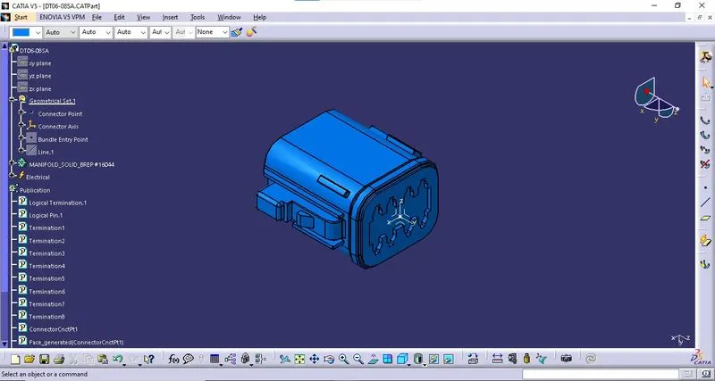
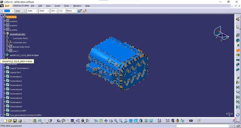
iii. Definition of Component:
The component is defined as the connector using "Define Connector" tab in the "Electrical Part Workbench". The number of terminals is defined.
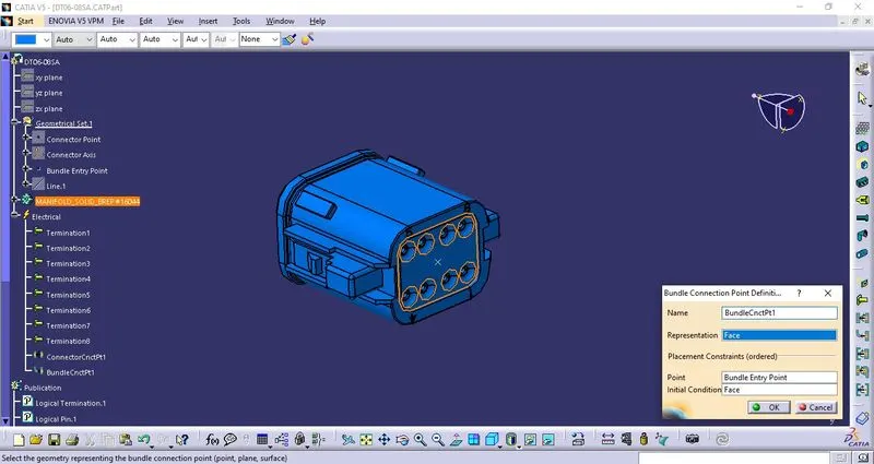
iv. Bundle Connection Point Definition:
The bundle connection point is defined using "Bundle Connection Point Definition" tab in the "Electrical Part Workbench". The parameters are defined appropriately.
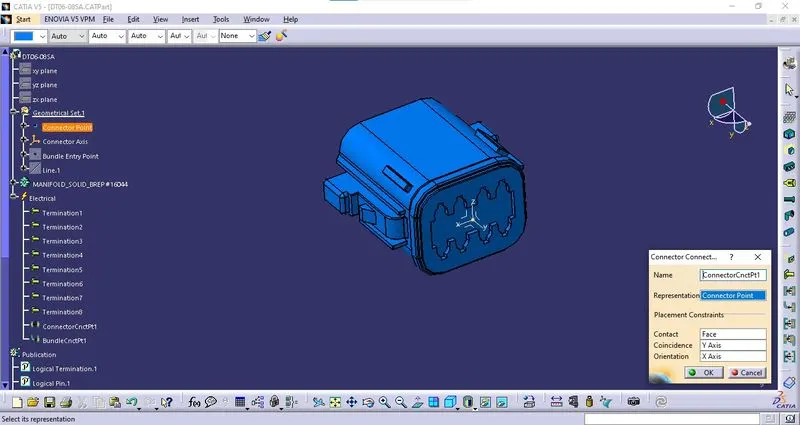
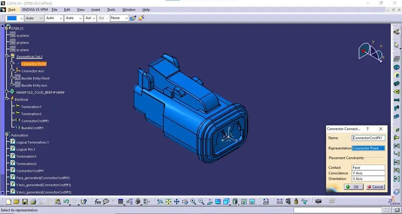
v. Connector Connection Point:
The connector connection point is defined using "Connector Connection Point Definition" tab in the "Electrical Part Workbench". The parameters are defined appropriately.
2. DT06-6S:
i. Download Connector 3D:
The 3D model is downloaded from the given link and saved as a Catpart file.
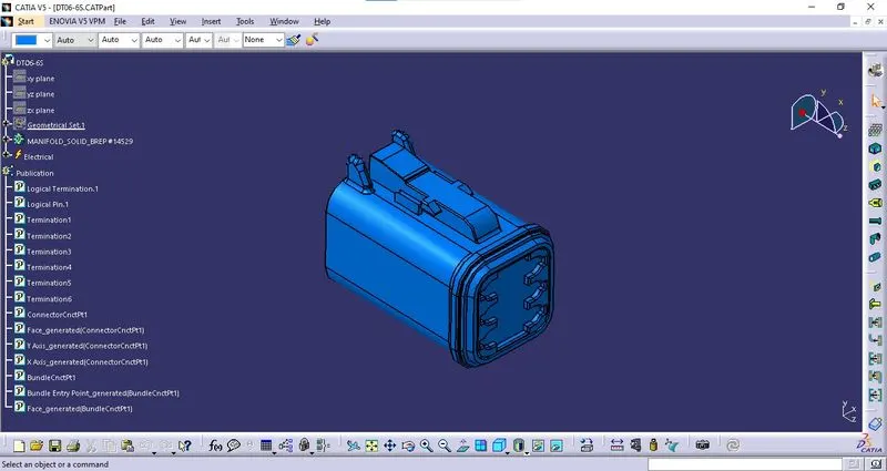
ii. Geometrical Parameters:
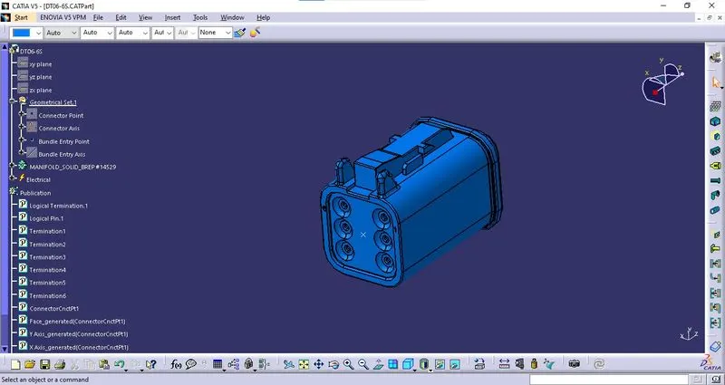
* Bundle Entry Point: The bundle entry Point is created at the rear part of the connector.
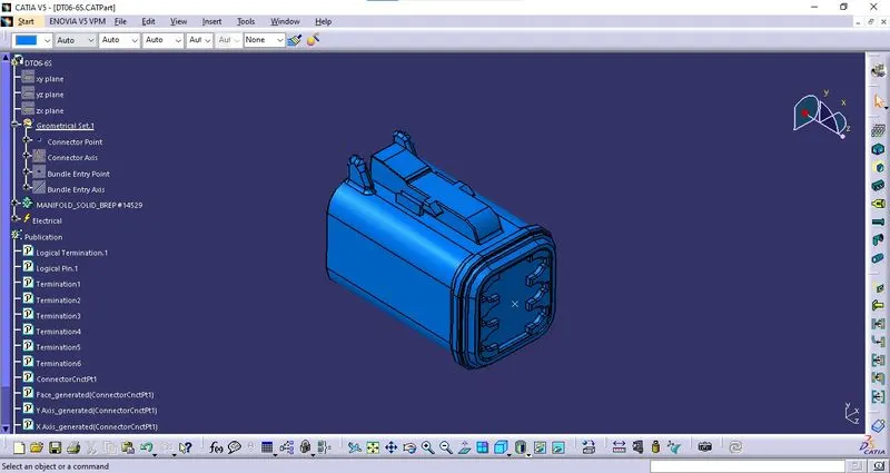
* Connector Point: The connector Point is created at the mating side of the connector.
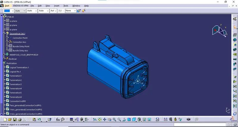
* Connector Axis: The connector axis is created with respect to Connector Point.
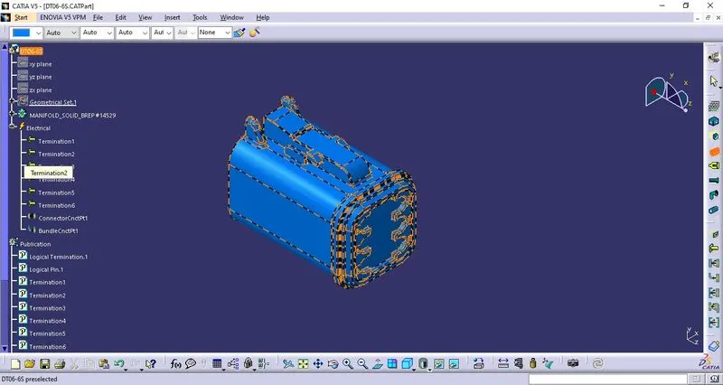
iii. Definition of Component:
The component is defined as the connector using "Define Connector" tab in the "Electrical Part Workbench". The number of terminals is defined.
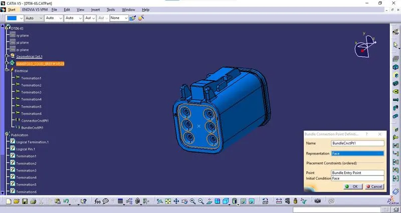
iv. Bundle Connection Point Definition:
The bundle connection point is defined using "Bundle Connection Point Definition" tab in the "Electrical Part Workbench". The parameters are defined appropriately.
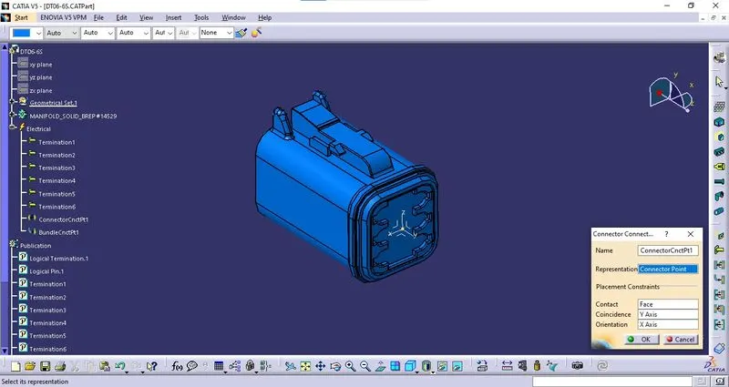
v. Connector Connection Point:
The connector connection point is defined using "Connector Connection Point Definition" tab in the "Electrical Part Workbench". The parameters are defined appropriately.
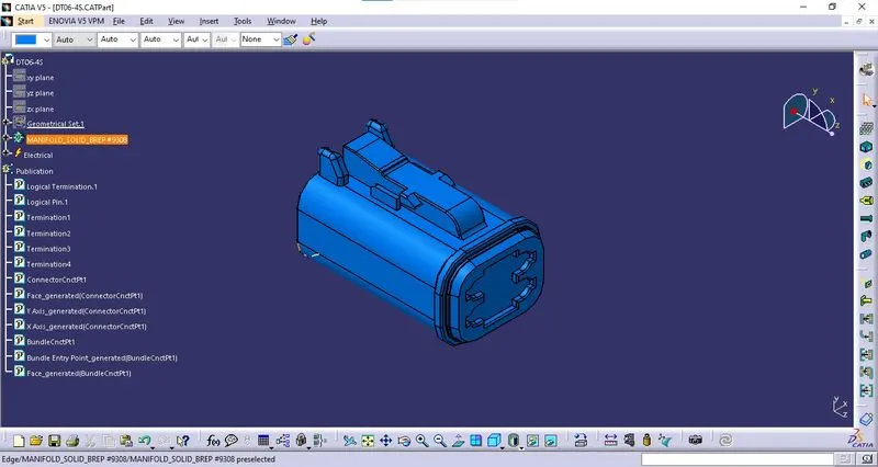
3. DT06-4S:
i. Download Connector 3D:
The 3D model is downloaded from the given link and saved as a Catpart file.
ii. Geometrical Parameters:
* Bundle Entry Point: The bundle entry Point is created at the rear part of the connector.
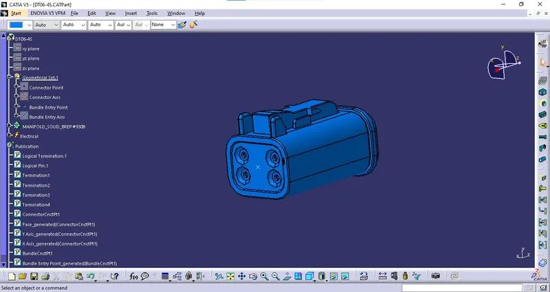
* Connector Point: The connector Point is created at the mating side of the connector.
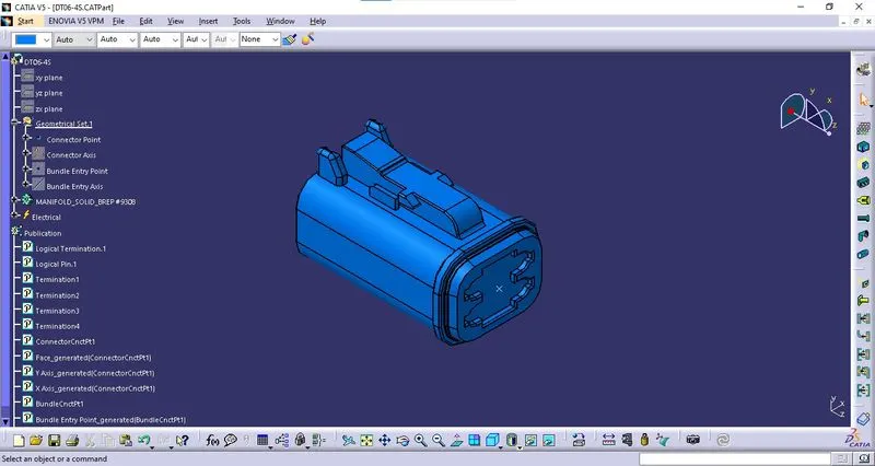
* Connector Axis: The connector axis is created with respect to Connector Point.
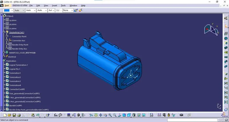
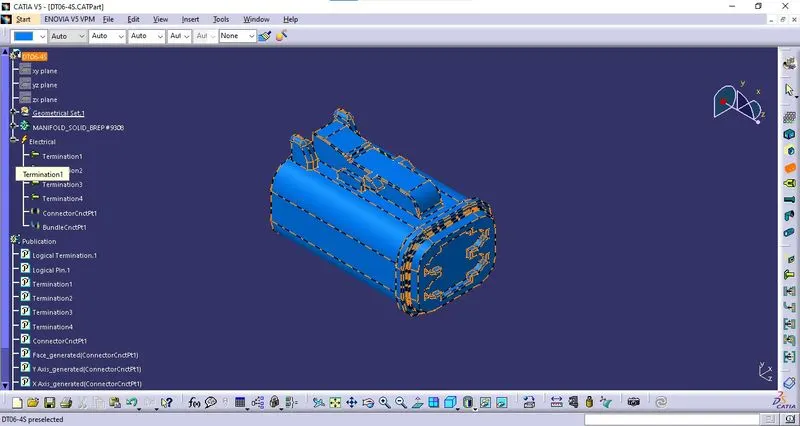
iii. Definition of Component:
The component is defined as the connector using "Define Connector" tab in the "Electrical Part Workbench". The number of terminals is defined.
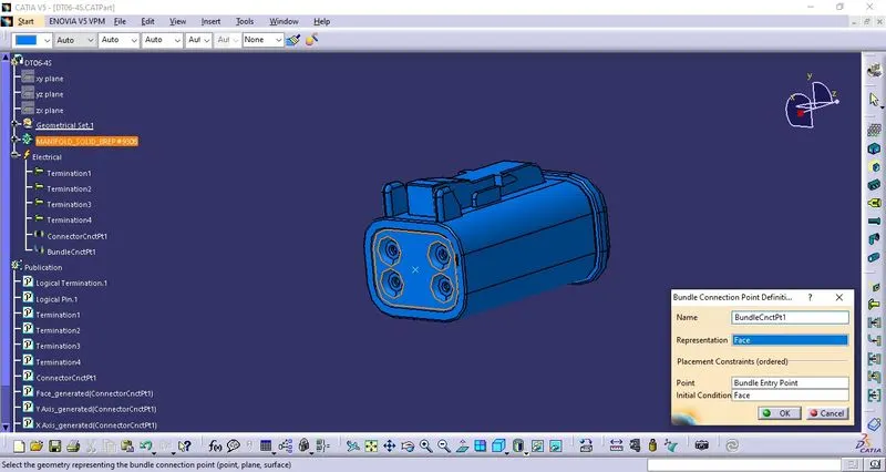
iv. Bundle Connection Point Definition:
The bundle connection point is defined using "Bundle Connection Point Definition" tab in the "Electrical Part Workbench". The parameters are defined appropriately.
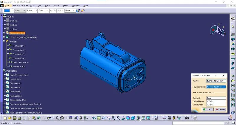
v. Connector Connection Point:
The connector connection point is defined using "Connector Connection Point Definition" tab in the "Electrical Part Workbench". The parameters are defined appropriately.
4. DT06-2S:
i. Download Connector 3D:
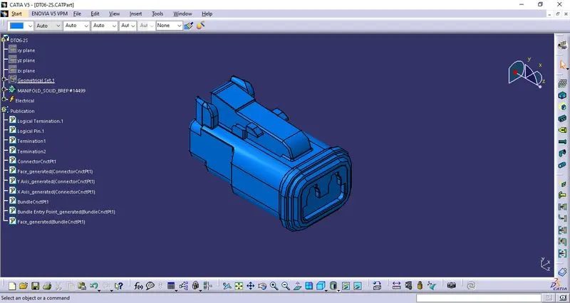
The 3D model is downloaded from the given link and saved as a Catpart file.
ii. Geometrical Parameters:
* Bundle Entry Point: The bundle entry Point is created at the rear part of the connector.
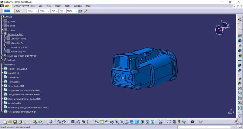
* Connector Point: The connector Point is created at the mating side of the connector.
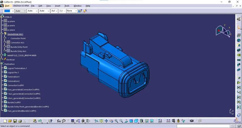
* Connector Axis: The connector axis is created with respect to Connector Point.
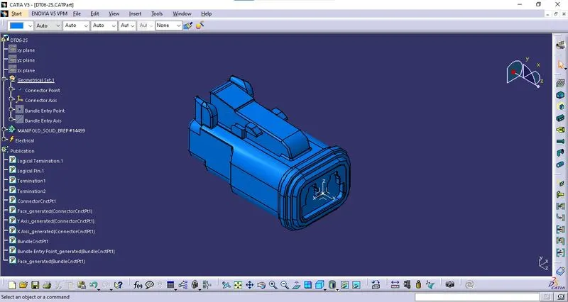
iii. Definition of Component:
The component is defined as the connector using "Define Connector" tab in the "Electrical Part Workbench". The number of terminals is defined.
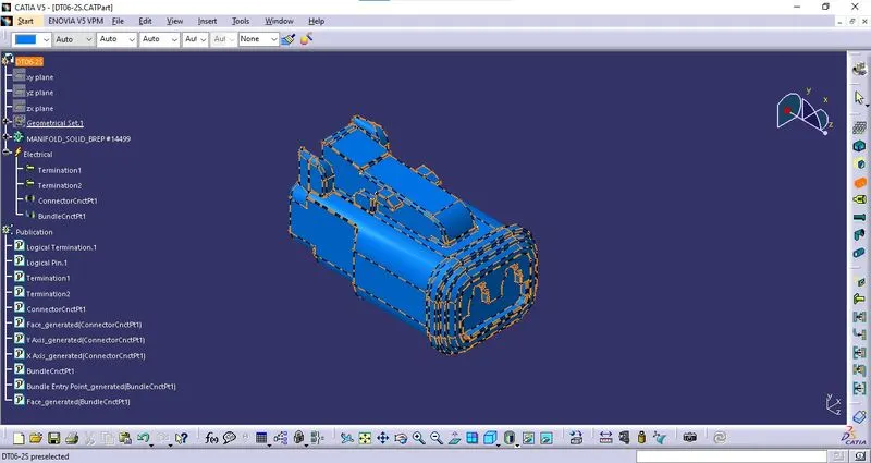
iv. Bundle Connection Point Definition:
The bundle connection point is defined using "Bundle Connection Point Definition" tab in the "Electrical Part Workbench". The parameters are defined appropriately.
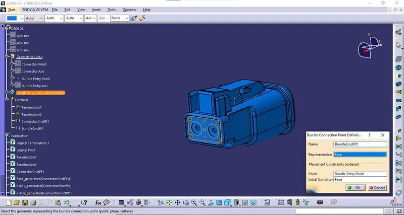
v. Connector Connection Point:
The connector connection point is defined using "Connector Connection Point Definition" tab in the "Electrical Part Workbench". The parameters are defined appropriately.
WIRING HARNESS ASSEMBLY:
i. Create Product File:
A new Product file is created with an appropriate file name.
ii. Create a Sub-Product File:
A new product file is created into the above-created product file by right click on Product file > Components > New Product. The file is named "Assy. Geometrical Bundle".
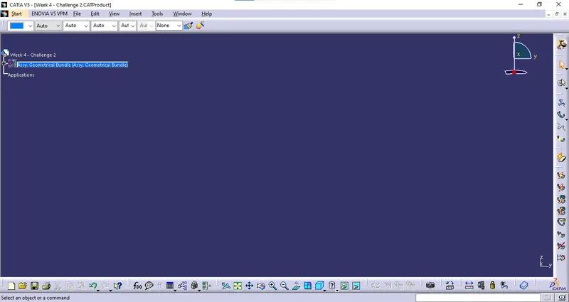
iii. Define Sub-Product Electrically:
The created Sub-Product is defined electrically by using the "Geometrical Bundle" option from the "Wiring Harness Assembly" workbench.
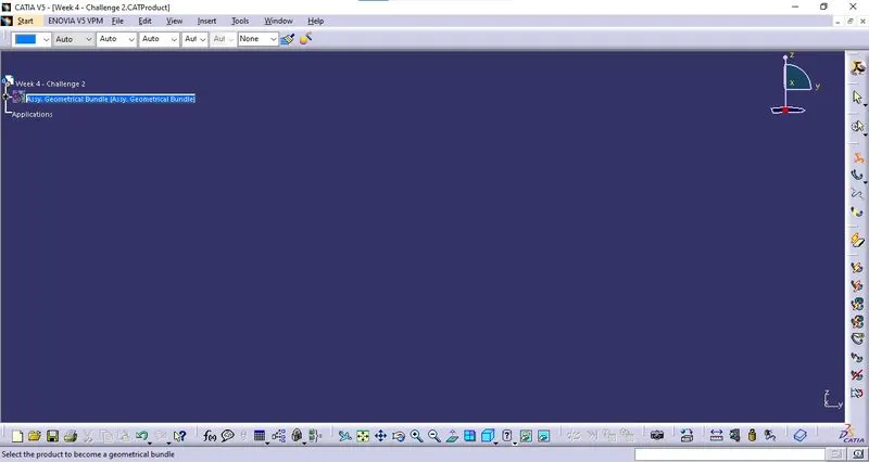
iv. Import Components:
All the required components as per the wiring diagram provided are imported into the "Geometrical Bundle" using the "Existing Component" option from the "Assembly" workbench.
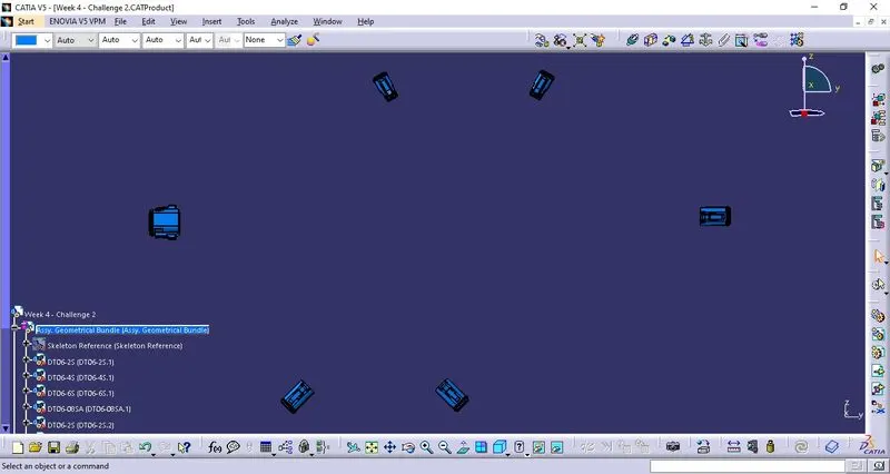
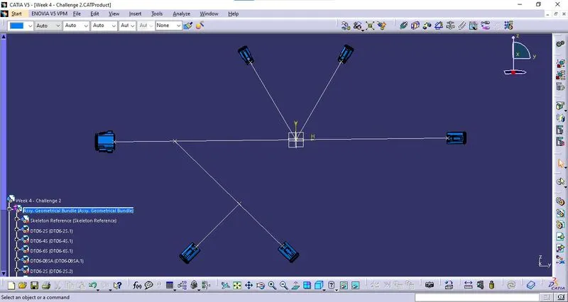
v. Locating Components:
The imported components are located at the correct location and orientation as per the requirement provided in the wiring diagram.
A reference sketch of the wiring diagram was created in the "Skeleton Reference" part file and it is used for bringing the connectors to the required position.
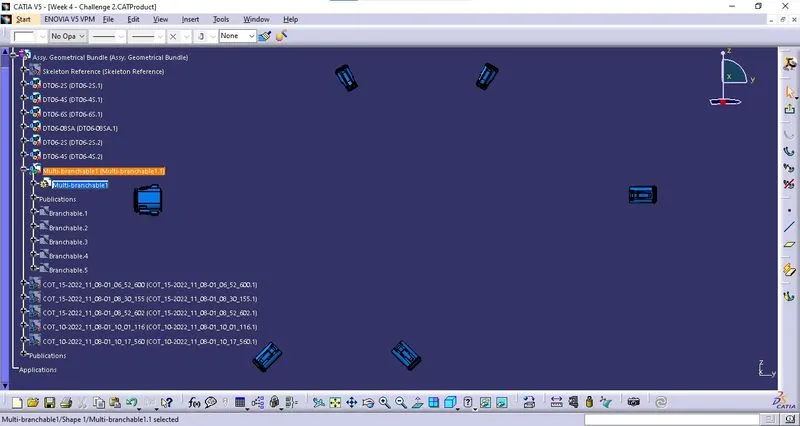
vi. Creating Wiring Harness:
The multi-branchable part is created by using the "Multi-Branchable Document" option from the "Wiring Harness Assembly" workbench.
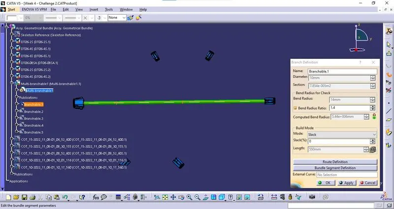
* Branchable 1:
Branchable 1 is created between DT06-08SA and DT06-6S connectors with a bundle diameter of 10mm and a bend ratio of 1.4.
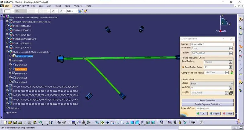
*Branchable 2:
As per the diagram, in Branchable 1, A Branch point is inserted at a specific location by using "Add Branch Point" option.
Branchable 2 was created in between the Branch point and DT06-4S.1 connector with a bundle diameter of 8mm and a bend ratio of 1.4.
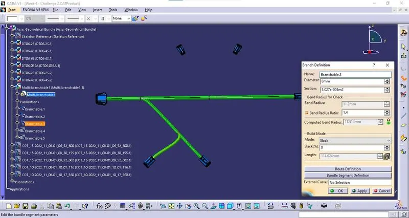
*Branchable 3:
As per the diagram, in Branchable 2, A Branch point is inserted at a specific location by using "Add Branch Point" option.
Branchable 3 was created in between the Branch point and DT06-4S.2 connector with a bundle diameter of 8mm and a bend ratio of 1.4.
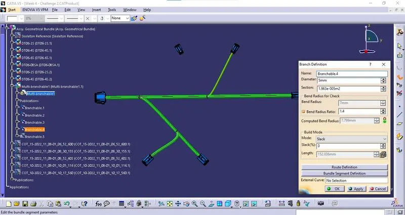
*Branchable 4:
As per the diagram, in Branchable 1, A Branch point is inserted at a specific location by using "Add Branch Point" option.
Branchable 4 was created in between the Branch point and DT06-2S.1 connector with a bundle diameter of 5mm and a bend ratio of 1.4.
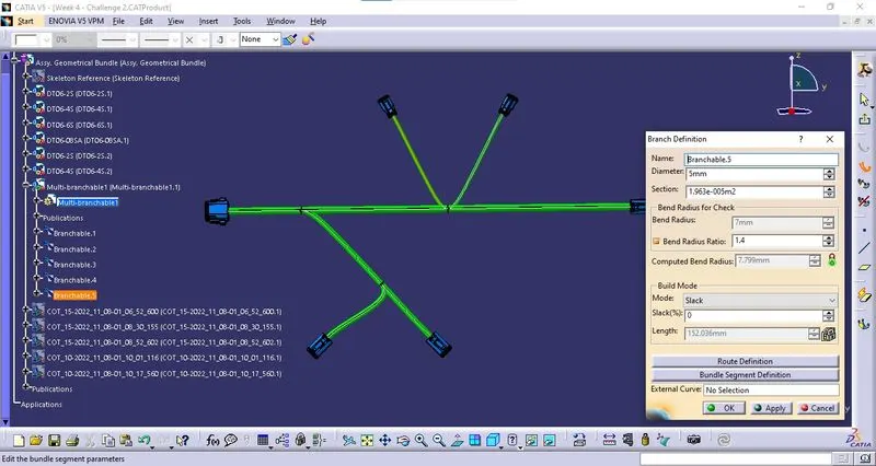
*Branchable 5:
Branchable 5 was created in between the Branch point and DT06-2S.2 connector with a bundle diameter of 5mm and a bend ratio of 1.4.
vii. Creating Protective Covering:
The protective covering for the wiring harness is used from the catalog created earlier.
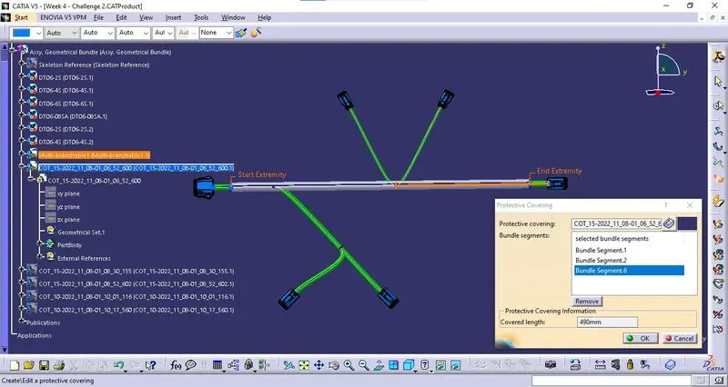
* COT 1:
The Corrugated Tube from the catalog is used on Branchable 1 with a diameter of 15mm and the Start & End Extremities are defined as 30mm from the connectors.
* COT 2:
The Corrugated Tube from the catalog is used on Branchable 2 with a diameter of 15mm and the End Extremitie is defined as 30mm from the connectors.
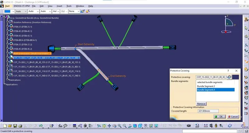
* COT 3:
The Corrugated Tube from the catalog is used on Branchable 3 with a diameter of 15mm and the End Extremitie is defined as 30mm from the connectors.
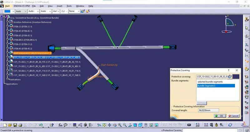
* COT 4:
The Corrugated Tube from the catalog is used on Branchable 5 with a diameter of 10mm and the End Extremitie is defined as 30mm from the connectors.
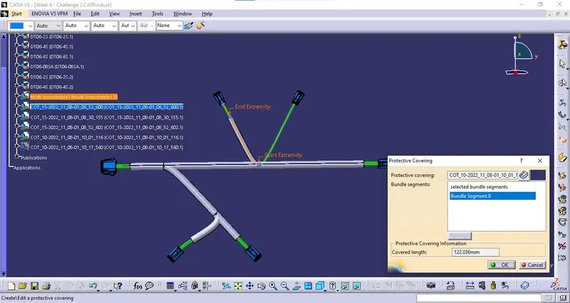
* COT 5:
The Corrugated Tube from the catalog is used on Branchable 4 with a diameter of 10mm and the End Extremitie is defined as 30mm from the connectors.
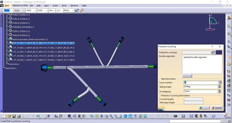
viii. Save the File:
The above-said product file is saved using the "Save Management" Option. All the required parts and product files are saved at a defined location.
OUTPUT - WIRING HARNESS ASSEMBLY: