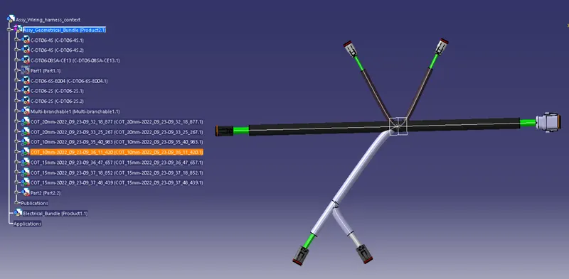
Wiring harness design in CATIA V5 - 3D modeling Week 4 Challenge
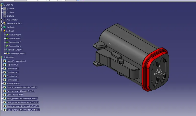
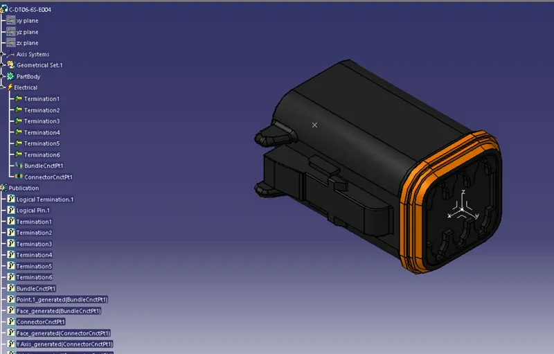
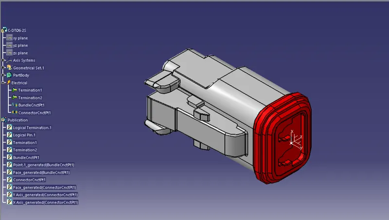
Following Connectors CAD files are downloaded from the site www.te.com
- DT06-4S
- DT06-6S
- DT06-2S
- DT06-08SA
Saved the CAT.part of all components and defined electrically.
DT06-4S
DT06-6S
DT06-2S
DT06-08SA
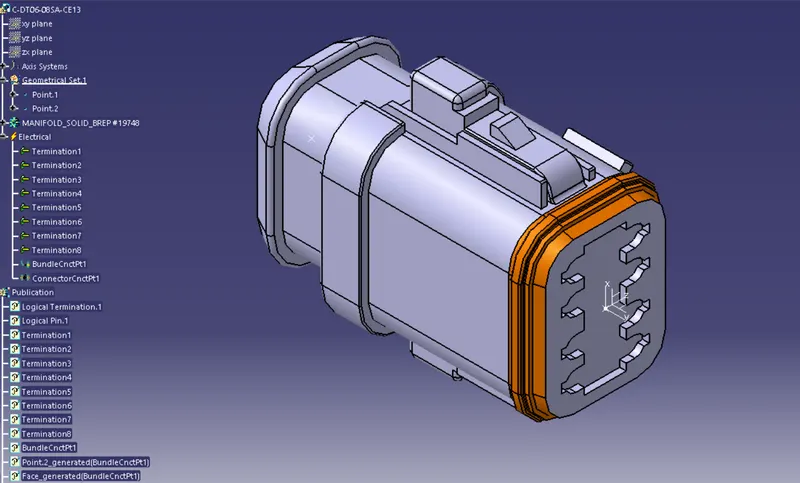
All the Connectors are added to the connectors catalogue.
Routing the given harness Layout;
- Created the main assembly product file, named Assy_wiring_harness_context
- Then created 2 sub products inside it, Assy_geometrical_bundle and Electrical_bundle.
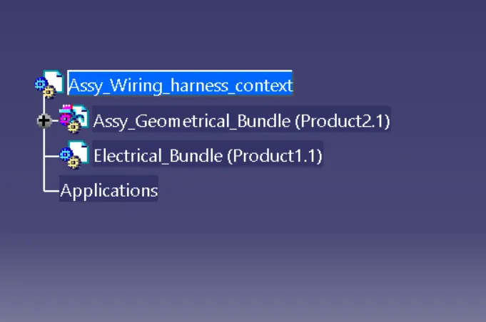
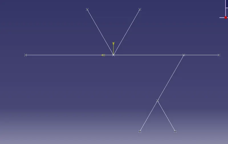
- Inside the assy_geometrical_bundle Created a reference sketch for the layout considering all the dimensions.
- Then added all the connectors into the same product file and placed all the components as per the layout given.
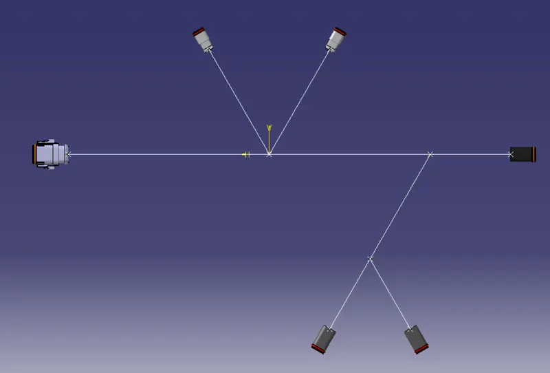
- These all are done in mechanical assembly design.
- Now we jump to Electrical harness assembly work bench and define the product as electrical assmbly.
- Using geometrical bundle command defines the assembly as electrical assembly.
- This is the very first step to do. otherwise we are not able to rout the assembly.
- Ensure all the components are inserted before starting the routing.
- Click on the command multi-branchable document, It will create a new part file and jumps to the Electrical harness installation work bench.
- Then go for the command branch definition.
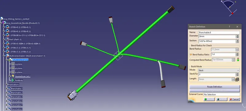
- provide the needful datas like diameter, bend radius and Build mode.
- Then go for the route definition option.
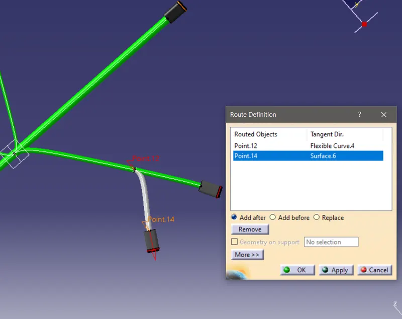
- it will give you a option to select routing objects, select the components to make connection.
- To create sub branches use the command add branch point to split the wire.
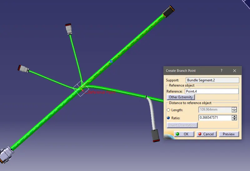
- After selecting the support branch to split, provide the length or ratio to position the split.
- Then we can add the sub branches at the split.
- After completing the connection we can exit from the Electrical Harness Installation workbench.
- And will jumps to Electrical Harness assembly workbench.
- Now we have to provide the protective covering.
- So go for the command 'protective covering', it will open a tab
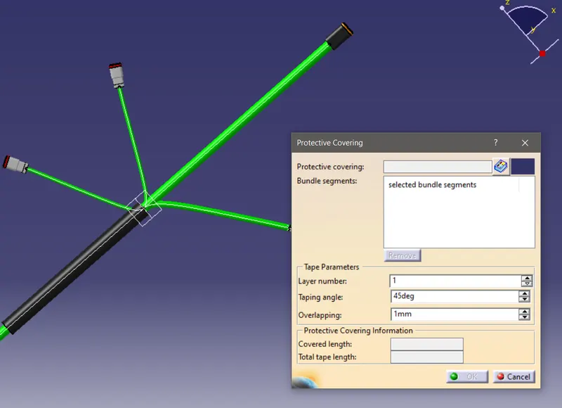
- Select the corrugated tube respective to the wire thickness.
- End extrimity of all the protective covering is given a 30mm gap from the connectors.
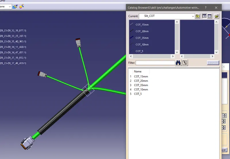
Figure below shows the picture of the completed work.