Wiring harness design in CATIA V5 - 3D modeling Week 4 Challenge
Step 1:
* We have to give geometrical properties to all connectors and define them electrically in electrical part design workbench in CATIA V5.
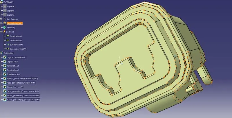
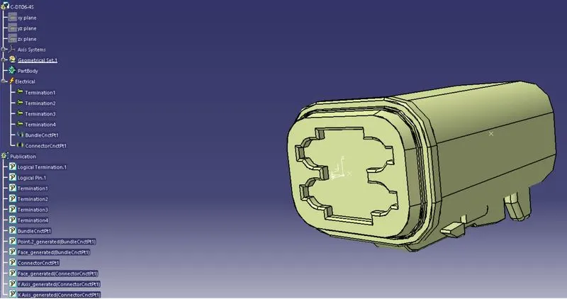
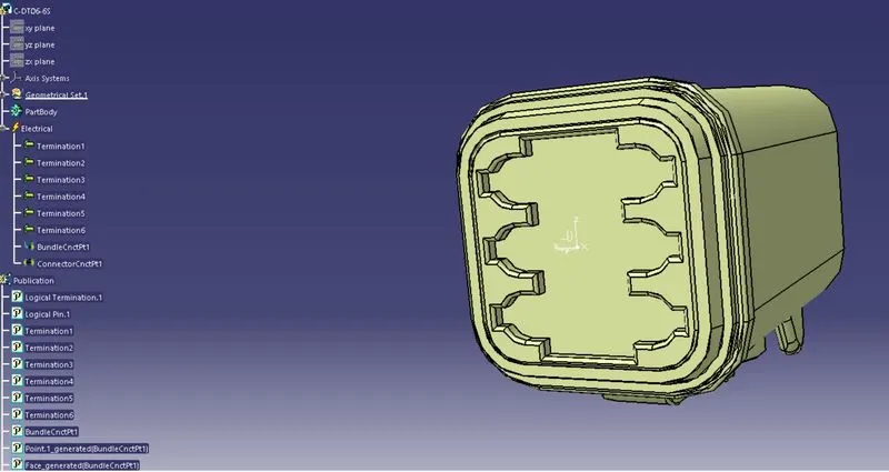
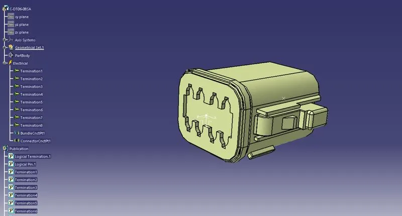
* We have dsigned all the connectors geometrically and electrically and electrically as shown in above images.
Step 2:
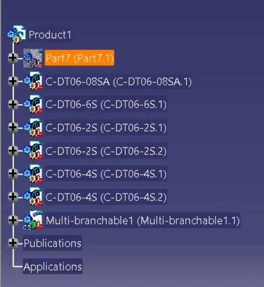
* Now we have to add all the components/connectors in 'Geometrical bundle assembley' in mechanical assembly design workbench
* Before that, we have to create 'Context assembly' as main product file and after that create two sub product files named as 'Geometrical bundly assembly' and ' Electricall bundle circuit'.
Step 3:
Next we have to locate all the connectors accordig to the given harness layout in assembly design workbench.
After we can add metal plate at background and hide it later
Step 4:
* Let convert mechanical assembly to electrical assembly by selecting 'Geometrical bundle' command in electrical harness assembly workbench.
* After wehave to creaete bundle segment(where assumed diameter is 12mm) between the connectors DT06-08SA and DT06-6S /
Step 5:
* After we have to create branch point and add another bundle segment(assumed diameter is 8mm) to join two connectors.
Step 6:
* After similarly add next branch point and create another bundle segment(assumed dia 8mm) to join connectors
Overall Wiring Harness Bundle Assembly:
* The overalll represetation fo wiring harness assembly.