Wiring harness design in CATIA V5 - 3D modeling Week 4 Challenge
AIM:
To download the connector’s 3d data from the website and to define them as electrical part and route the bundle between them with their desired positions, according to the below diagram.
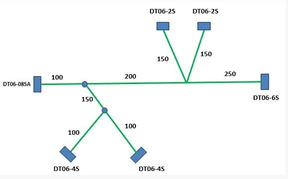
PROCEDURE:
First we have to download the cad data for the following parts from the website www.te.com
- DT 06-2S
- DT 06-4S
- DT 06-6S
- DT 06-08SA
Then convert the part electrically by using the electrical part design work bench by following below steps.
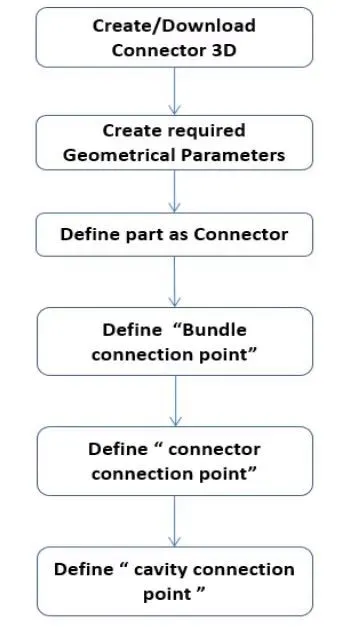
Define the part as connector, and select the number of terminals.
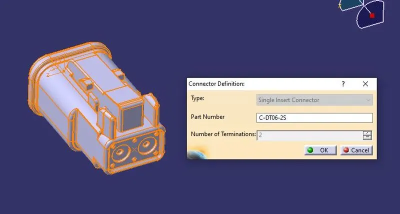
Define the connector connection point.
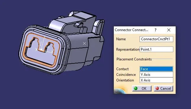
Define bundle entry point.
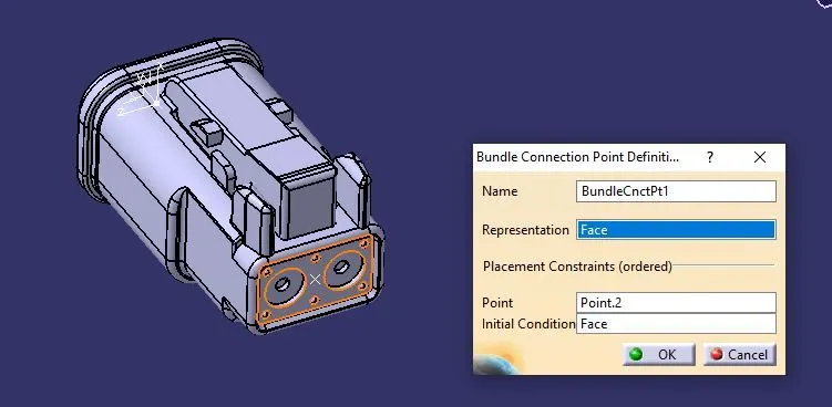
here we are not using the clip mounting so we are not defining the clip mounting. By following the same above methods we need to define all the other connectors also.
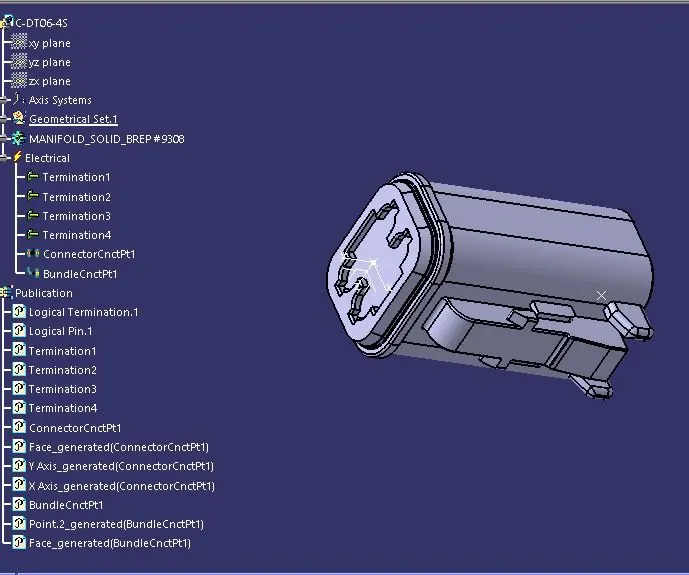
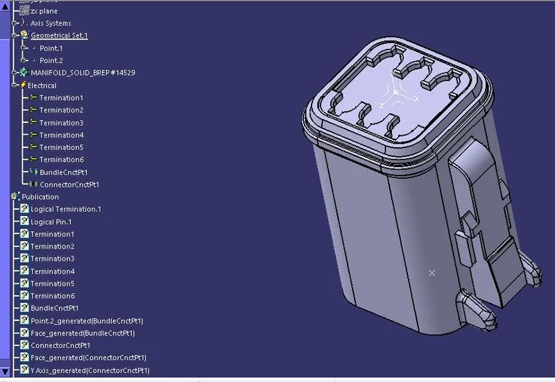
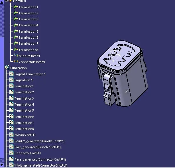
After defining the parts electrically then we need to insert all the electrically defined components, and place them on their desired locations. Then we need to select the geometrical bundle command and define the product electrically. Then we need to use the multi-branchable command and in that workbench we can route the bundle between the connectors and other devices.
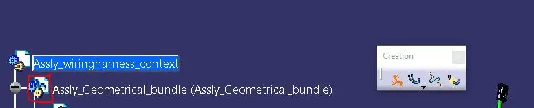
We need to select the Geometrical bumdle command in the Electrical harness assembly workbench, and select the product file. After selecting the product file we can see the change in the icon of the product file.
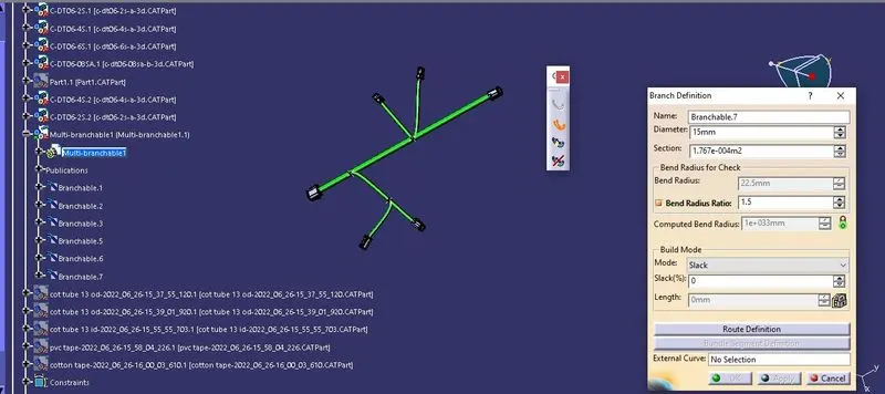
Then we have to create the multibranchable command in the same work bench, after selecting the multibrachable command we will be rerouted to the electrical harness installation workbench, here we can select the Branch definition command , and also we can add the sub branch in the main trunk (branch).
After creating the branches between the parts wee need to add the protective covering on the electrical harness assembly window, from the catalog we have saved already.
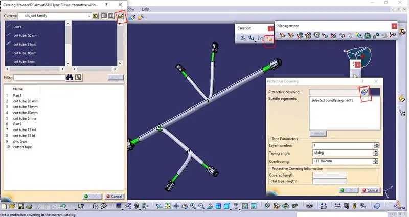
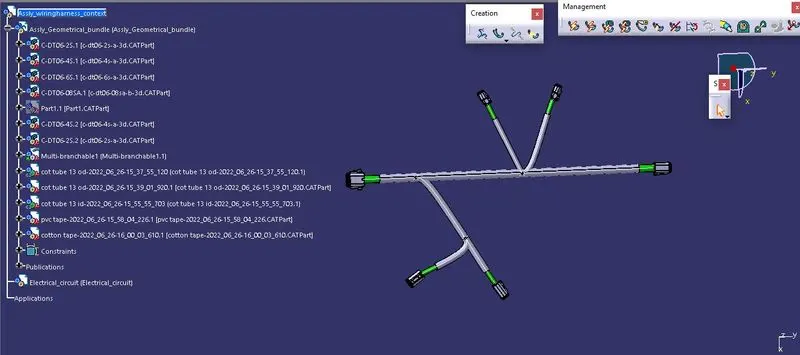
We can also select the extrimities of the starting and end point of the cot tubes from the connectors we can also select the pvc or cotton tapes also for protective covering. By follwing the above steps we can create the wiring harness assembly.
Conclusion:
Thus the connectors and all parts are defined using the various electrical work benches and the total wiring harness assembly is also created.