Wiring harness design in CATIA V5 - 3D modeling Week 2 Challlenge
Good Evening,
Report on Connector Definition
Objective:
To define the necessary properties of given electrical components DT06-08SA, 174357-2, 85229-1. Using CATIA V5- electrical part design, electrical harness assembly and mechanical assembly workbench by downloading the cad file and defining the geometry parameters, connector, bundle, cavity connection points of parts. These above defined parameters are used when they are routed to the electrical connector.
Introduction:
Connectors: Electrical connectors are an electro-mechanical device used to join electrical termination and create electrical circuits. They are plastic moulded housing with locking and retention features. This are responsible to make contact between wiring harness and components or between two different wiring harness assemblies by offering mechanical locking and sealing to the joint. It consists of housing, terminals, wedge locks, seals, cavity, mounting cam….etc.
Retention device: It’s like connector mounting clips, connector secondary locks are respective use to provide mechanical fixing, locking to the connector and terminals. Connector and back shells are used for good appearance and bundle dressing in critical areas.
Clips & Clamps: They are used to fix wiring harness bundles by providing positive fixings. These are widely used for harness clamping in every area of vehicle. These plastic moulded parts with mounting and snapping features.
Methodology:
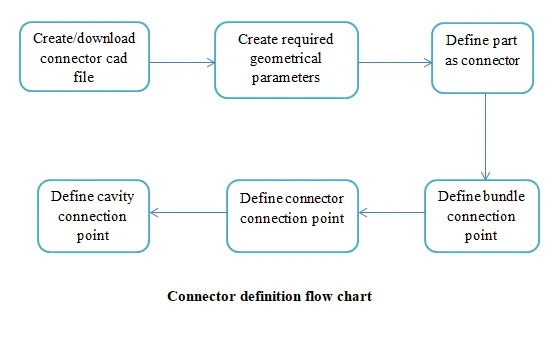
Following parameters are required to define for any connector:
Geometry parameter: points and axis system.
Connector connection points: this points used for connection of one connector to another connector.
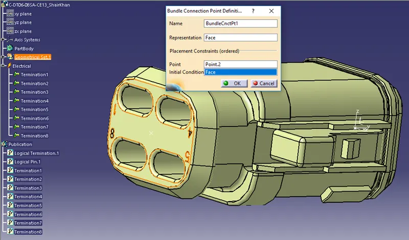
Bundle connection point: this point defines where the harness bundle segment point will end when routed to the electrical connector.
Cavity connection point: this point is used to define the connection of a connector clip. This only applies to connectors which have the mounting feature for connector clip.
Procedure:
Taking above given electrical component connector C-DT06-08SA-CE13 Following the similar procedure but it varies with components and fuction of components.
1) C-DT06-08SA-CE13 : housing for female terminals
1.Download the CAT file from the given link which is in the form of zip file and extract the file. Drag the extracted file to CATIA V5 workbench.
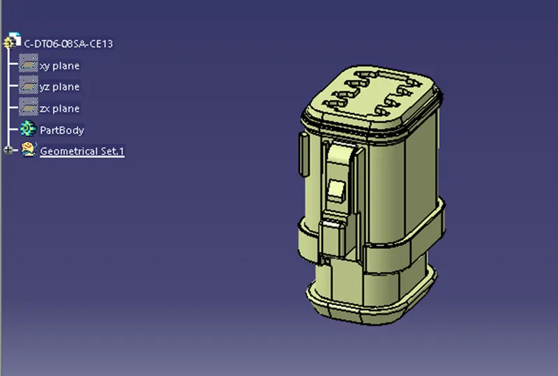
It appears in electrical part design workbench. And open in mechanical part design workbench. Save it as .CAT part. And define electrical part.
Open in mechanical part design workbench and define geometry parameters point and axis system.
2. Defining point at mating face and bundle face:
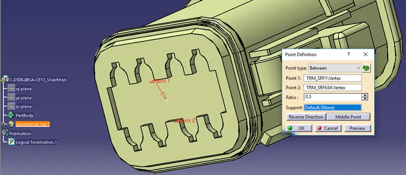
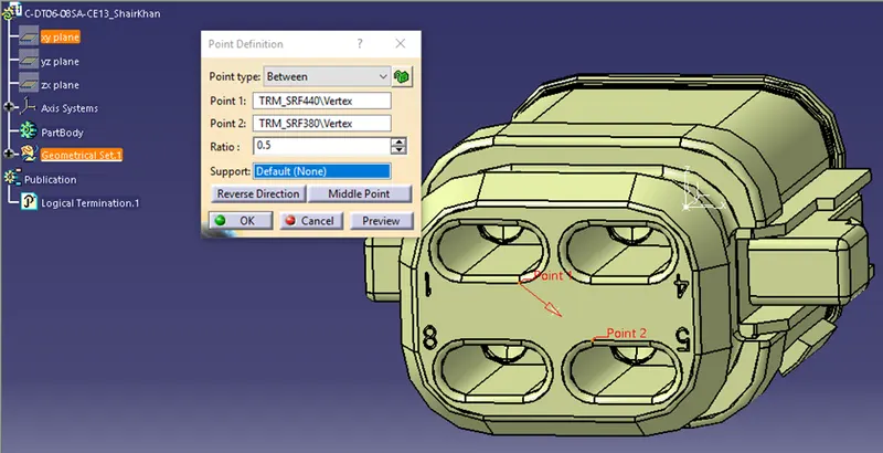
And Axis system at mating face:
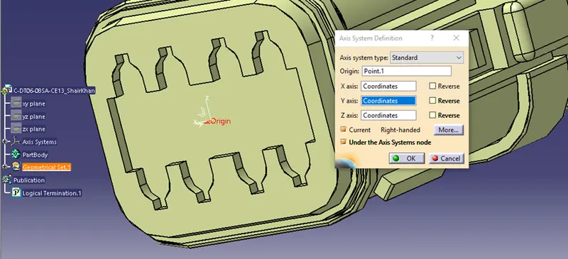
Making sure that the direction of x, y, z axes are in same direction for mating face of both the connectors and which are mating it has to be same. Here x axis is orientation, y axis coincidences.
3.Defining part as connector:
In electrical part design workbench defining as connector and define terminals based on present at bundle side connection.
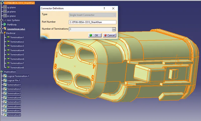
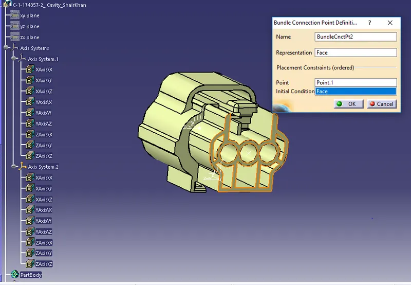
4. Defining bundle connection point:
Select the bundle entry point and face, from bundle entry side.
5. Defining connector connection point:
At mating face as previously defined axis system and point is used as representation point which is known as connector connection point, y axis as coincidence, x axis as orientation, and face for mating.
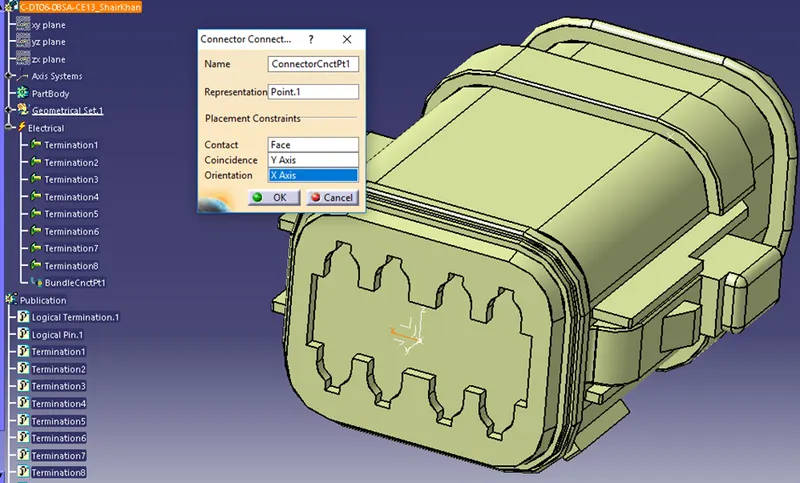
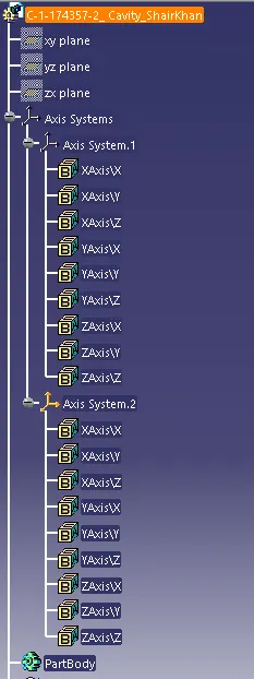
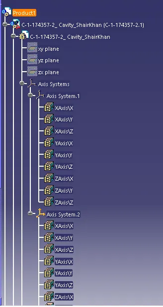
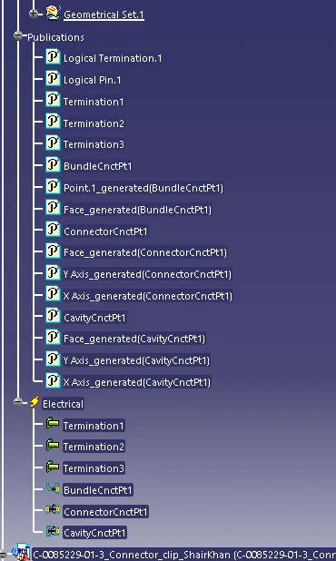
Expanded tree
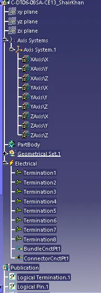
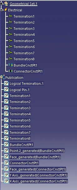
2) 174357-2 : housing for female terminals
Geometry point and axis system
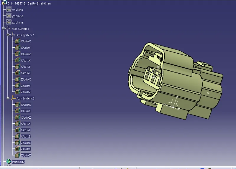
By selecting the curve at the bundle side and making a point of bundle connection and at the mating side point and axis system at the middle of the face and similar to cavity point.
2. Defining as connector:
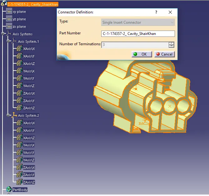
3. Bundle connection point:
4. Defining connector connection point:
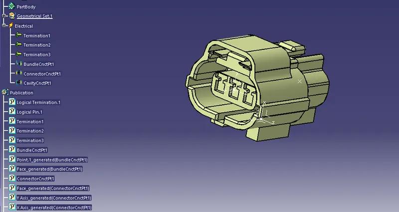
Middle point as representation, x axis as orientation, y axis as coincidence, and mating face.
5. Cavity connection point:
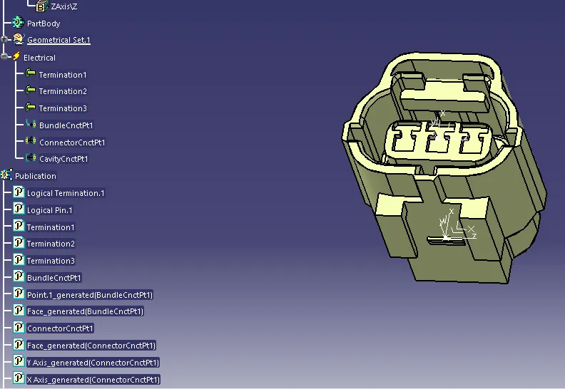
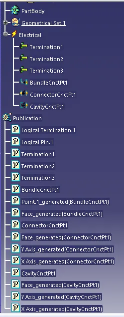
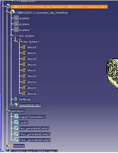
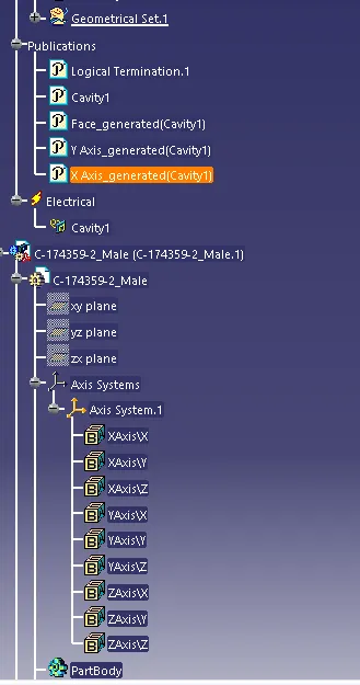
Expanded tree
3)85229-1: mounting clips
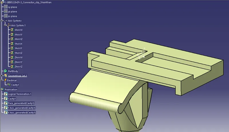
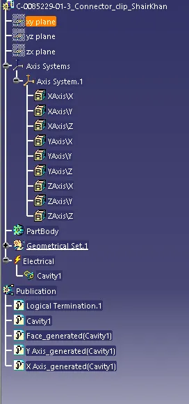
1. geometry has define at the edge of clip connector.
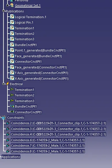
After assembly the components in electrical harness assembly workbench:
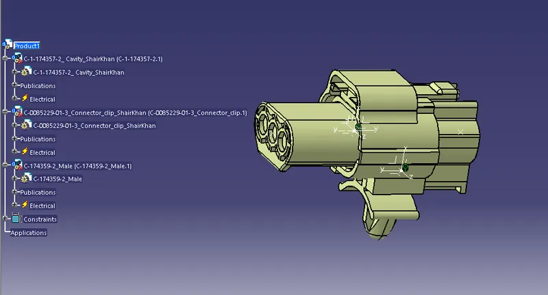
Expanded tree
Conclusion: we concluded that defining the CAT part into electrical part by defining parameters are required to defined for any connectors. using CATIA V5 electrical part design workbench. And by assemblying them it gets constrained.