Radar Mast & Final Assembly of Yacht
Good Evening,
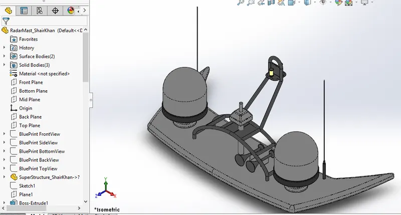
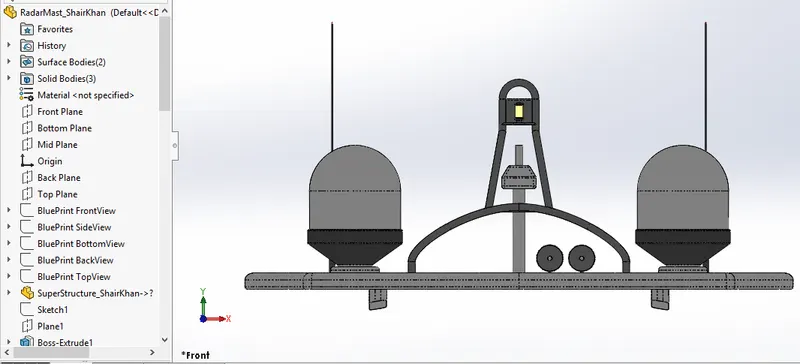
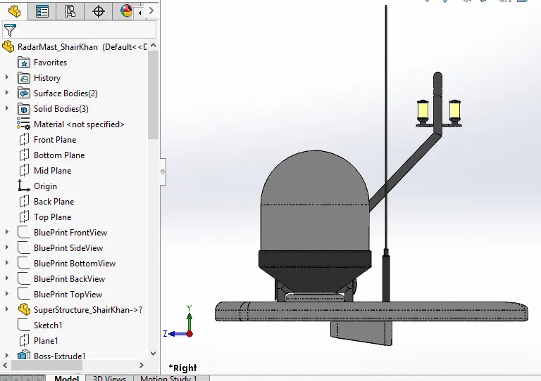
1) Radar Mast
Iso view
Front view
Right view
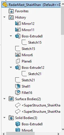
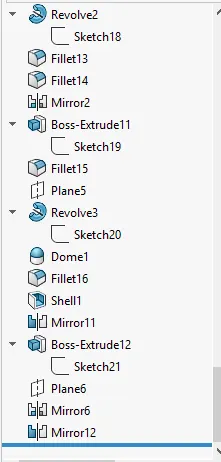
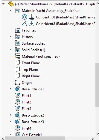
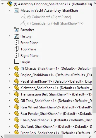
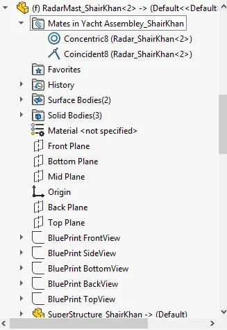
Expanded tree
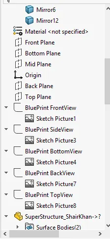
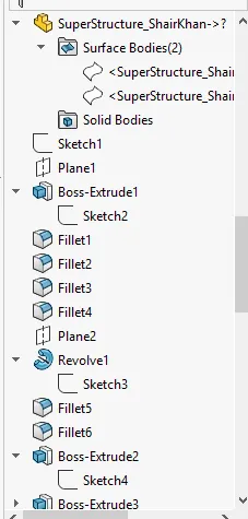
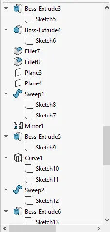
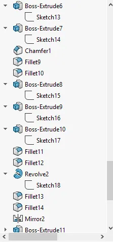
2) Assembly of Yacht model
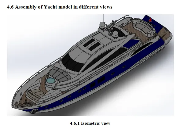
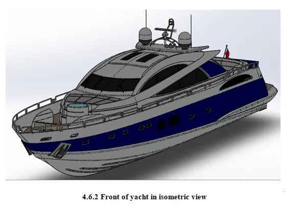
Iso view
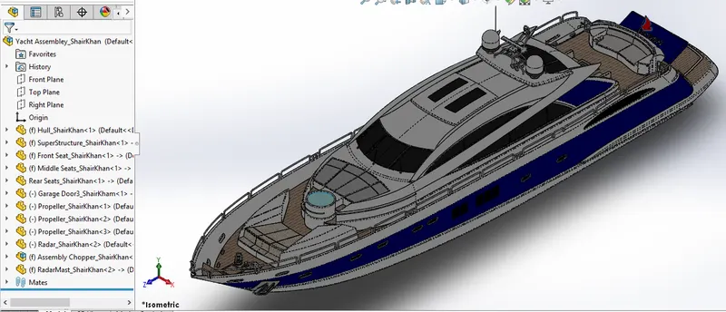
Right view
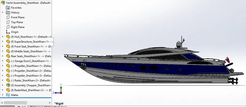
Top view
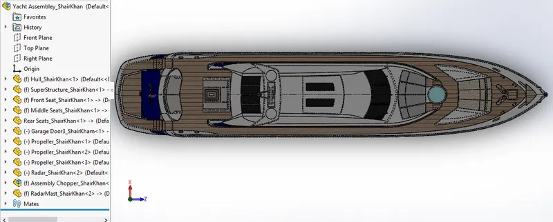
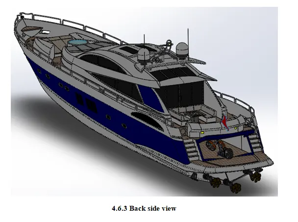
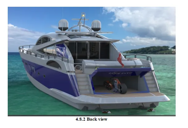
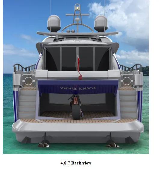
Back view
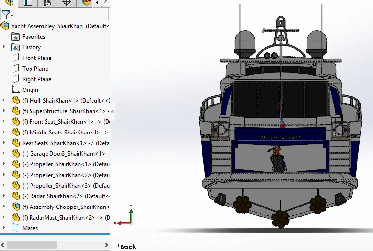
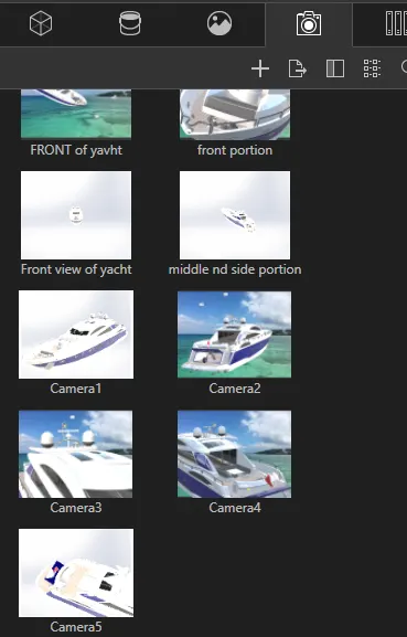
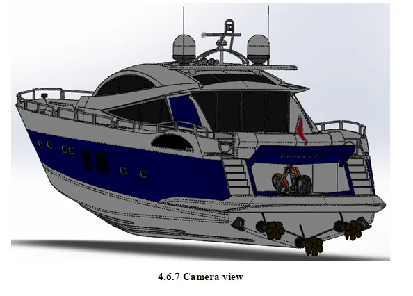
Camera views
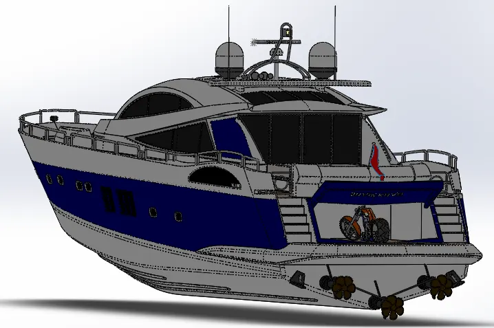
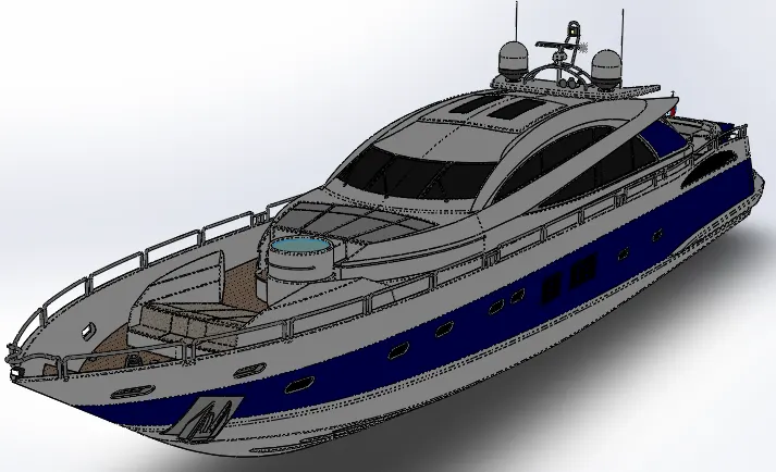
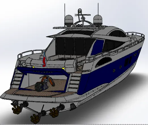
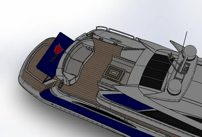
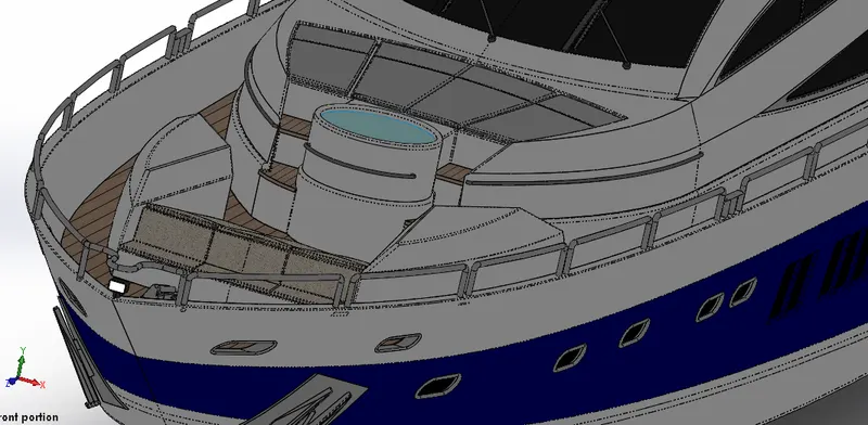
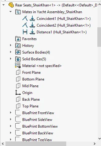
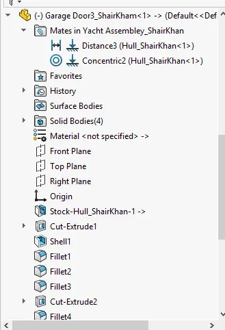
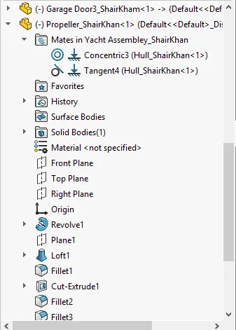
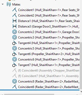
Expanded tree
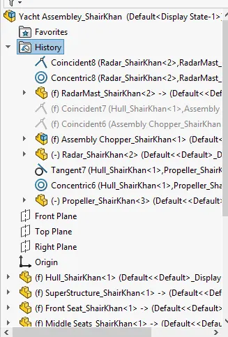
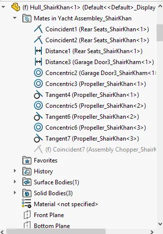
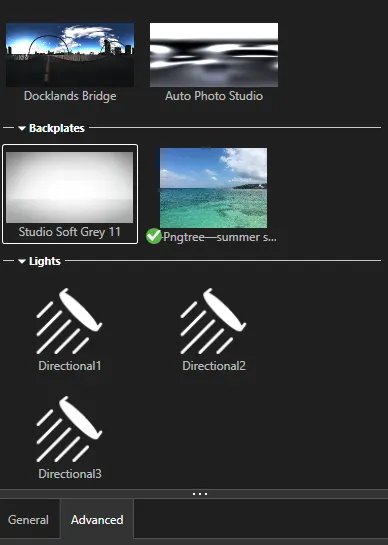
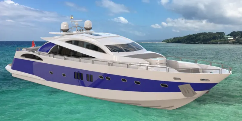
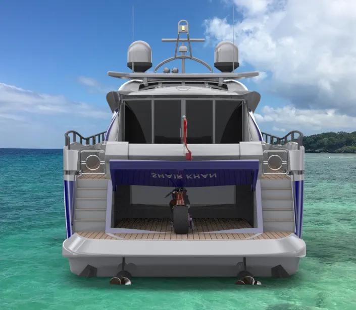
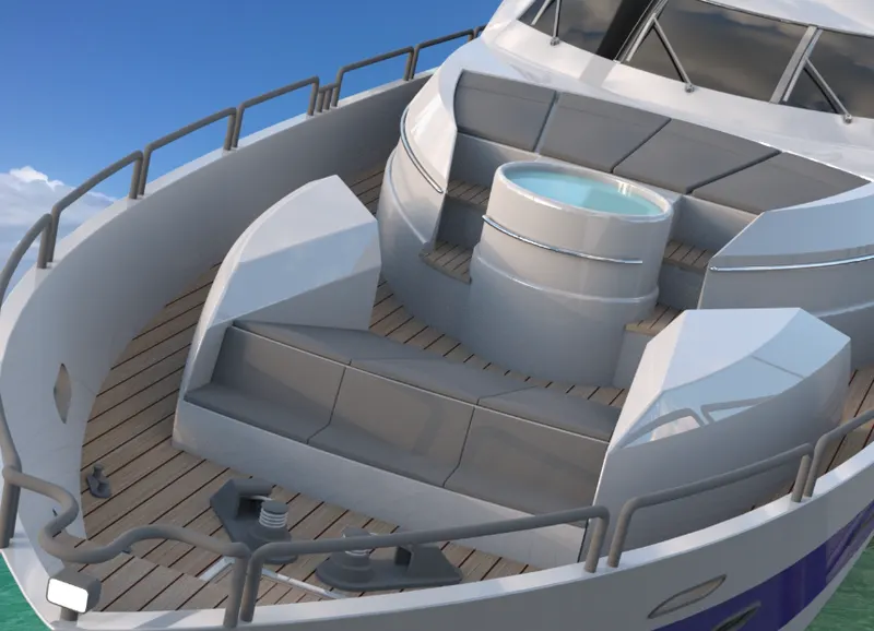
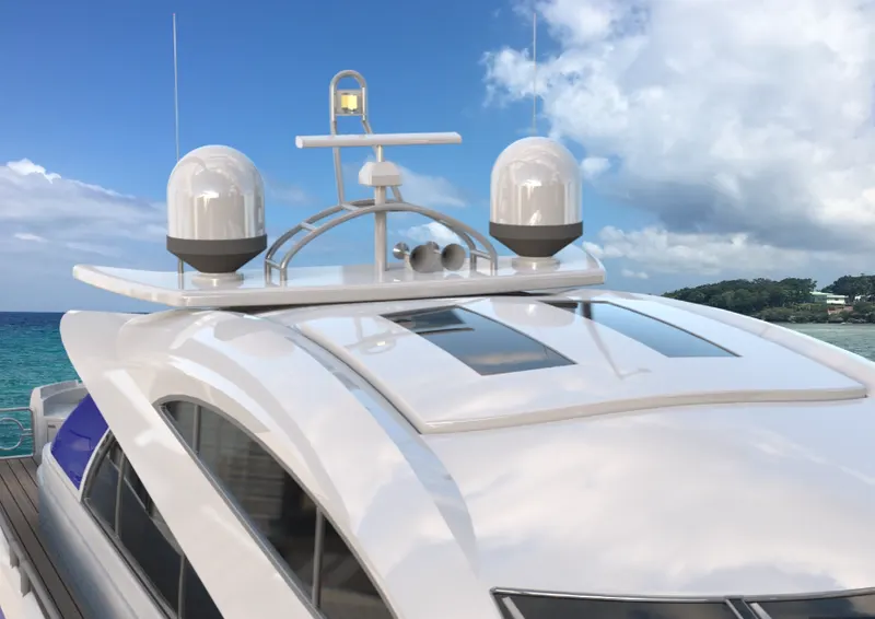
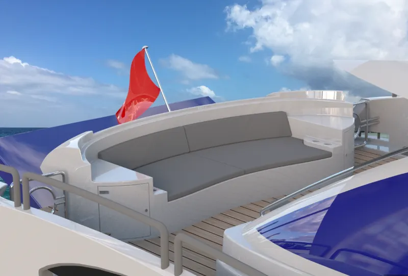
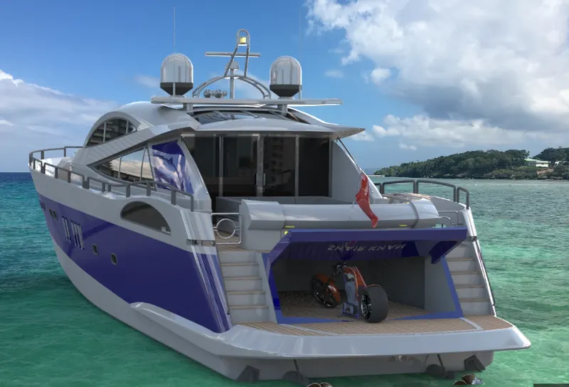
Rendering yacht assembly
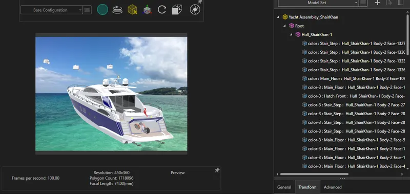
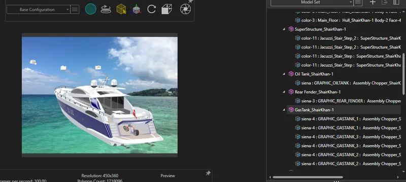
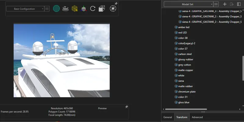
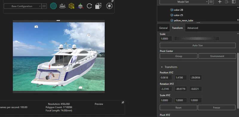
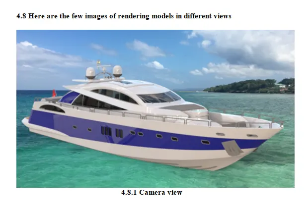
Rendered Images
Camera view
A Project Report On
“ASSEMBLY OF YACHT MODELLING USING ULTIMATE SOLID WORKS AND RENDERING”
1.Objective
Understanding the designing and sketching in two dimensions to 3 dimensions modelling the any desired components using design software like solid works, Auto Cad….etc.
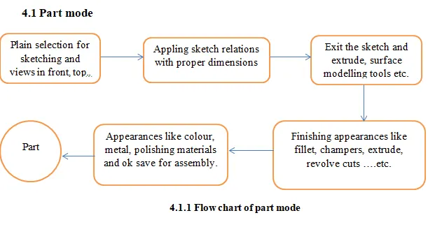
Using dimensions and giving the relations to the sketch with help of tools. Modelling the sketch with surface, extrude, cut …etc. Constraining the sketch and giving the desired output of a component. With appearances and assembly them with other components and give them best outlook appearances and visualizing the background, scenes and rendering.
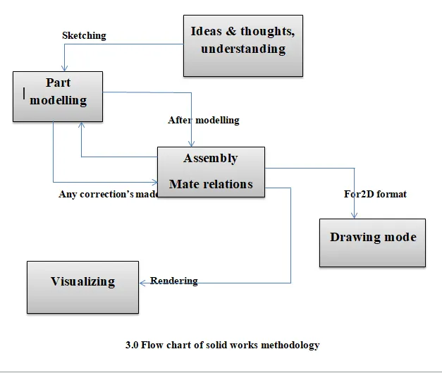
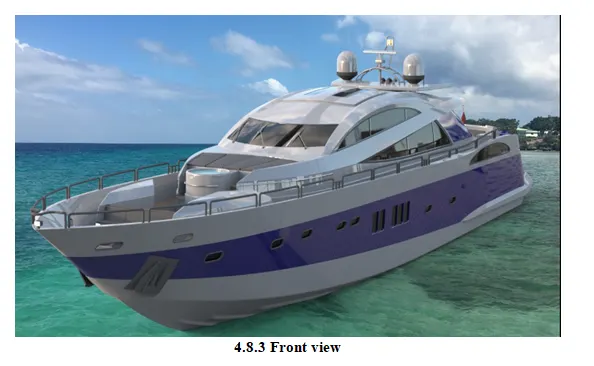
In this project we are constructing and designing the yacht model using Solid works 2018 software. For rendering the final assembly by setup of environment, background, scenes, lightings….etc. in Solid works visualizing for photo360view.
2. Introduction
CAD stands for computer aided design. Used in almost any kind of industries, engineering companies it’s very important in being the successful product.
Solid Works is powerful and convenient design software to design 3D models of mechanical parts and assembling, drawing to manufacture and understand the behaviours.
Solid Works is a 3D solid model based on computer aided design system. Solid works mechanical design automation software is a feature based, parametric solid design tool sketch out ideas, experiment with features and dimensions, and produce modelling and detail drawings
Its structure in three basic types
- Part mode
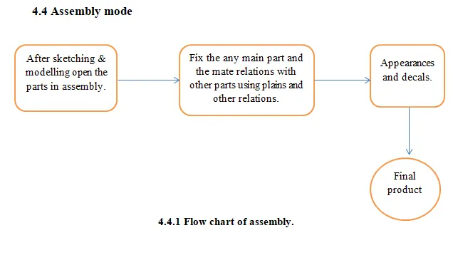
- Assembly mode
- Drawing mode
It utilize parametric based features, parameters refer to constraints whose value will determine the shape of model, assembly. Which are length, tangency, and angle, coincident…etc.
3. Design Methodology
Using above modes and tools, relations we will be designing the sketches environment of the part in plains for base feature. Exit the sketch mode and boss extrude, surfacing tools for design and analysing the part with physically appearances like metal, fabric, paint…etc. Combining or assembling the part using relations like angle, coincident, perpendicular … etc. drawing in 2D formats like reports according to the input parameters. And final setups, back plates, environment and scenes to look realistic view of model.
4. Description
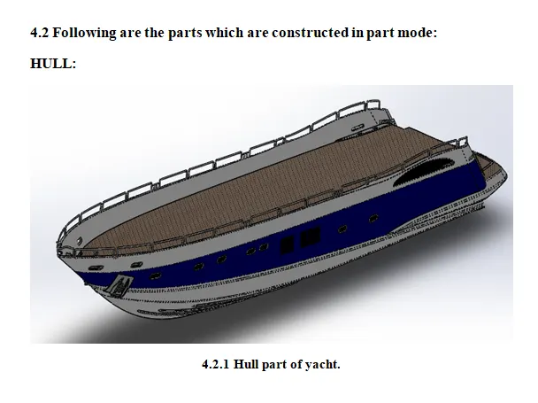
Hull: We use blue print setups front, bottom, back, side, top views and planes.
In sketching 2D, 3D: Spline, line, arc, smart dimensions, curves, projected curves, surface loft, surface trim, surface extrude, knit surface, surface fill, shell, offset, trim, fillet, champers, extrude cuts, rectangle, straight slot, planes, sweep, swept surface, delete, split the body or delete or keep body, mirror.. And giving relations to sketch. Make upper surface of hull as a surface body used for further use. And edit decals to surface, stairs, and garage space.
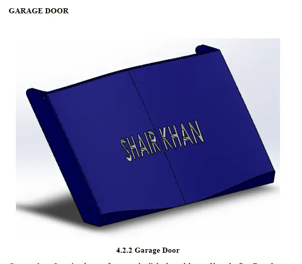
GARAGE DOOR: Inserting the part from saved split body or delete and keep bodies. Extrude cut, shell, and fillet, add text font style, plane reference, cut offset from surface, appearances, mirror. Tools and features are used.
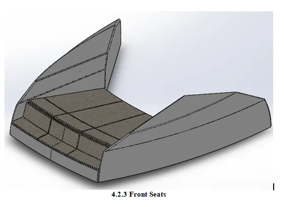
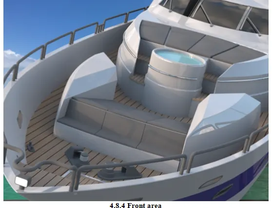
FRONT SEATS: Using blue prints making the position with the help of hull surface.
Spline, surface extrude, surface fill, surface trim, fillet, offset surface, extrude, dome, mirror, revolved, knit surface, appearance. Tools & feature used while constructing the front seats.
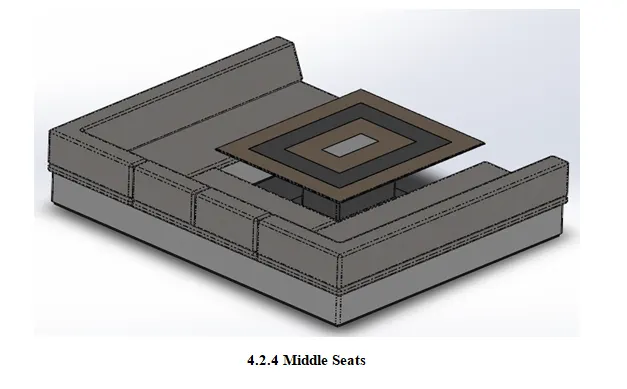
MIDDLE SEATS: Placing the position on the hull surface using blue print. Following the same procedure using line, rectangle, smart dimensions, extrude Bose, mirror, offset, plane, fillet, champers, and appearance. Tools & feature used while constructing the middle seats.
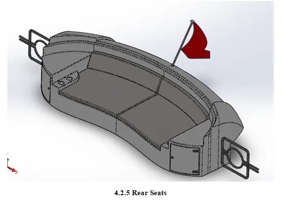
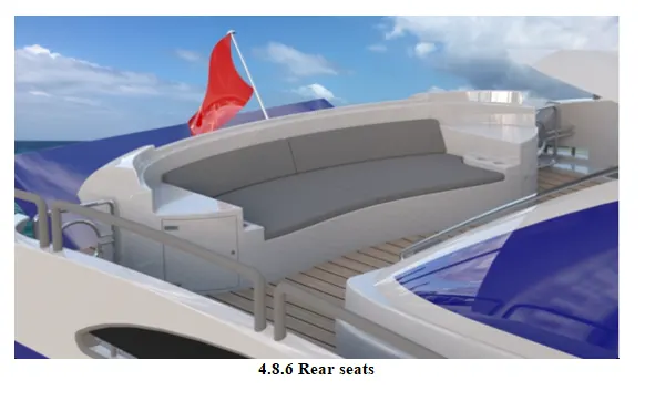
REAR SEATS: Following the position on hull surface using blue print setup. Spline, line, ruled surface, extrude surface, extend surface, trim surface, knit surface, extrude cut, extrude Bose, fillet, offset surface, champers, revolved Bose, 3D sketch, loft surface, appearance.
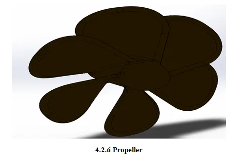
PROPELLER: Simple construction used in propeller like line, spline, revolved, curve pattern, fillet, cut, appearances.
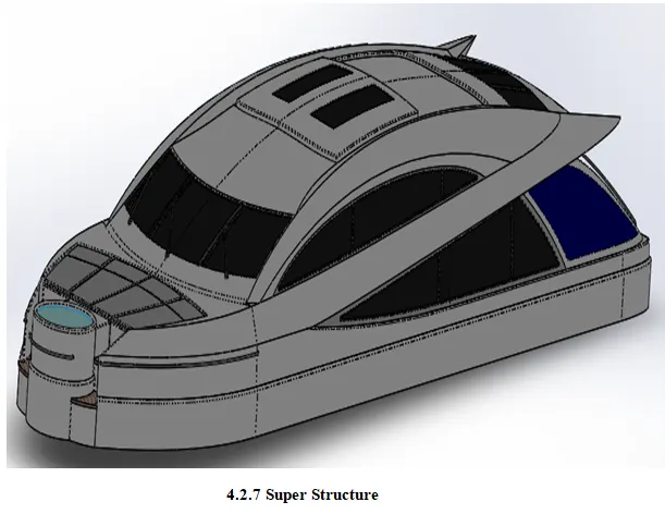
SUPER STRUCTURE: Following the blue print setup, hull surface for positioning the structure. line, spline, extrude surface, convert entities, extend surface, ruled surface, planes, surface loft, projected curves, trim, knit surface, delete face, offset surface, extend surface, extrude surface, cut, sweep surface, swept Bose, fillet, mirror, appearances, edit decals.
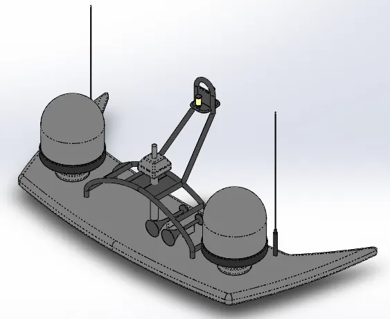
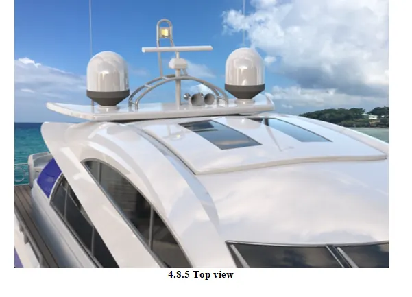
RADAR: Using line, extrude bose, cut, arc, hexagnol slot, mirror, extrude cut, text, appearances.
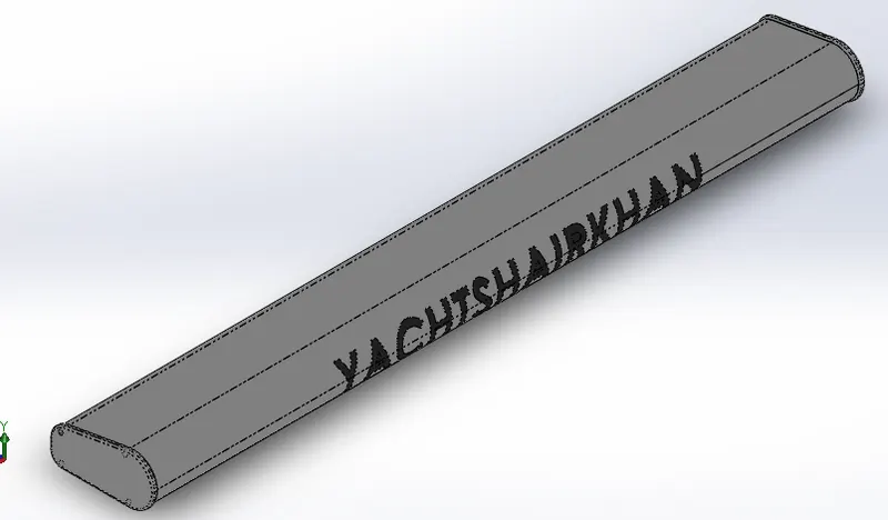
RADAR MAST: Using offset surface from the super structure upper surface with blue print. spline, line, revolved, extrude bose, projected curve, mirror, shell, appearances.
4.3 Tools and features
Line: To sketch, a line in vertical, horizontal, midpoint, construction, centreline…etc.
Spline: To shape the curve by giving the direction to arrows and weight to it.
Arc: To draw arc centre point arc, three point arc, to set the arc in either in reverse direction with radius.
Rectangle: To draw either in corner, centre, midpoint etc. drag with set of dimensions
Circle: To draw circular objects with radius values.
Smart dimensions: To give the dimensions to the sketch like length, angle….etc.
Select: This option used for selecting edges, entities... etc. to give relation like tangent, parallel, perpendicular, coincident relations.
Unit system: MMGS, CGS, MKS…. etc.
View orientation: To view the sketch and model in isometric, front, top, back, … customize the view using camera option also.
Hide: To hide any sketch or model.
Trim: To cut or erase and extend the sketch to the other end.
Offset: To offset any edge, shape … to either in inward or outward direction to get shape.
Mirror: To mirror the selected edges and curves to the centre line.
Linear pattern: To draw the sketch in line or curve pattern to get the shape of sketch using dimensions.
Block: To make block and place them in folder, insert the block and use multiple sketches by giving relations to them.
Extrude: To form any solid feature either in shape, by selecting the sketch.
Revolved: To form solid feature by an axis, revolve.
Swept: It sweeps the profile along the path to form solid feature.
Lofted: Add materials between profiles to create solid feature.
Boundary: Add materials between profiles to create solid feature in two directions.
Extruded cut: To cut the solid body in two directions.
Revolved cut: To cut the solid body along an axis of sketch.
Swept cut: To cut the solid body by sweeping profile along the path.
Fillet: Creates round, edges, faces to inward or outward of solid body or surface.
Chamfer: Creates the faces and edges in desired shapes by using dimensions.
Curve driven patterns: To create faces and bodies in circular direction.
Shell: Removes the material from solid body and make it hallow with thickness.
Reference geometry: Use of additional planes at any point, and an axis….etc.
Project curve: Adding the reference sketch in plain and using it in another plain to give the curve as per required.
Composite curve: Combining the project curves.
Dome: Adds one or more domes to the selected faces.
Sketch picture: Using as a reference image for sketching.
Split: To create multiple bodies with existing parts or separate.
Pierce: To make sketch and curve or plane coincident.
Merge: To make to two points into the same or one.
Coincident: To make any point or plane or body place on any point or plane or body or surface.
Concentric: To make any two circle a relation.
Parallel: Making any two lines in same direction.
Perpendicular: Making any two lines in opposite direction.
Angle: Making any two lines traveling in direction with degree.
Mate: Giving the two solid bodies a relation.
Appearances: Giving appearance or real look of solid bodies like paint, metal, fabric…etc.
Display state: Setting state or appearance or view in other than default state.
Decals: Applying graphic images to parts.
Camera view: To add camera from any selected view, adjust it by using distance and focal length, resolution…..etc.
Combining: Adding any two or more parts in one solid body.
Offset surface: Creates offset surface using one or more contiguous faces.
Extrude surface: Creates an extruded surface.
Revolved surface: Creates a surface feature by revolving closed or open profile around the axis.
Swept surface: Creates a surface feature sweeps the profile along the path.
Lofted surface: Creates a surface feature using two or more profiles.
Boundary surface: To create boundary surface between profiles in two directions.
Filled surface: Construct the surface path with in a boundary defined by existing model sketch, edges or curves.
Ruled surface: To insert ruled surface from edges.
Delete face: To delete a face from solid bodies to create surfaces.
Extend Surface: To extend the edges, multiple edges or the faces on a surface based on end conditions and extension type.
Trim surface: Trims a surface where one surface intersects with another surface a plane, sketch.
Knit surface: To combines two or more adjacent non-intersecting surfaces together.
Thicken: Creates a solid feature by thickening one or more adjacent surfaces.
Photo360view: Enable to add decals, lights, directions, scenes setups, and preview.
Integrated preview: Displays the photo360view preview inside the solid works graphics area.
Final rendering: Invoke a photo360view final rendering.
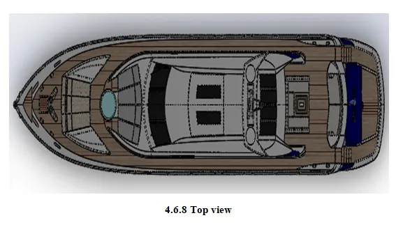
4.7 Visualizing
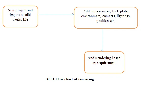
To make the assembly appearance’s looks in a realistic in nature.
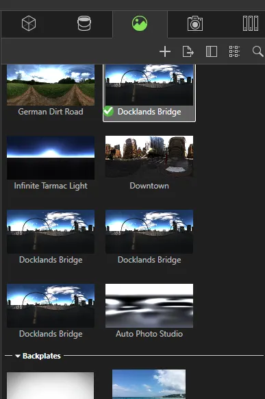
We use solid works visualizing software for photo shop of assembly by setting up the cameras, backgrounds, scenes, environmental HDR images setups.
And then rendering, it will give the high resolution of image with given input parameters like environment, camera ….etc.
5. Conclusion
In this project we learned, sketching in 2D and converting into 3D modelling. Using part mode for sketch and modelling the part, making the sketch constrain with proper dimensions and relations. Extrude, revolve, cut, split, fillet…etc. using different tools and feature, making surface model in 3D and shell to the part. Good understanding the surface use of tools and features to make any 3D or complex material using solid works, blue print setup. And knitting the surfaces of non-intersecting surfaces and making solid body.
Assembly use different relations of mating with other parts of assembly, appearance, materials adding. Setup the camera and different views, background settings.
Making the assembly photo realistic looks, using rendering in solid works visualization with setups and environmental background, scenes and render in different views.
THE END