Wiring harness design in CATIA V5 - 3D modeling Week 2 Challlenge
Objective:- Electrically defining the given connectors & connector mounting clips.
1. Connector: Deutsch DT06 – 08SA
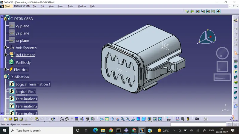
2.Connector: Tyco 174357-2
Steps involved in electrically defining a connector
- Download a connector from TE / Tyco website igs or stp format.
- Unzip the connector in destination folder.
- Save as CAT part in the folder
- Rename geometrical set as Reference element
- Define reference elements such as bundle connection point, connector connection point, cavity connection point by taking the between option in the point command with middle option.
- Bundle Connection Point.
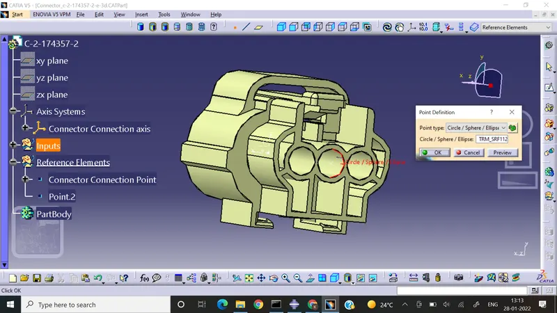
- Cavity connection Point
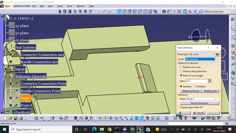
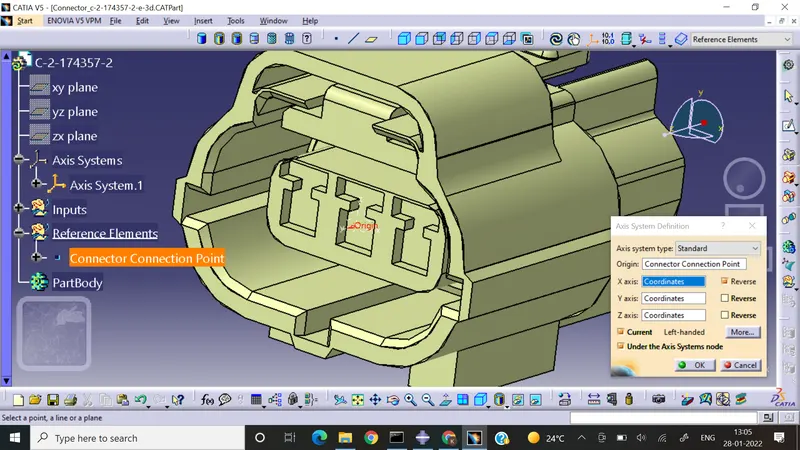
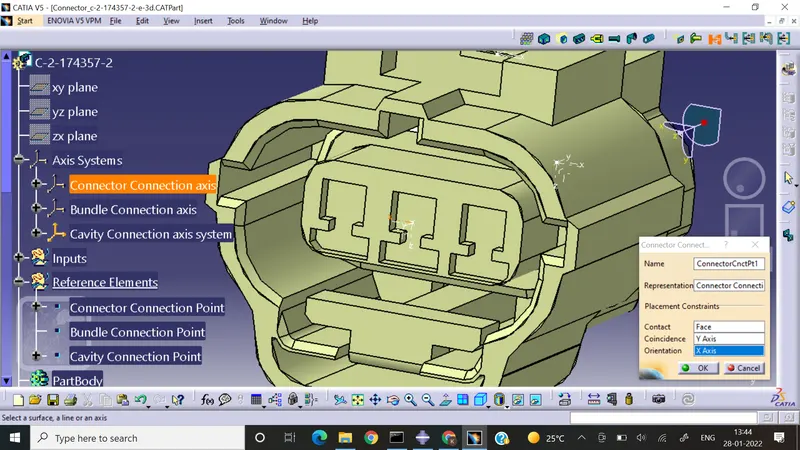
- Define the axis of the connector connection point & Bundle Connection Point. The Y-axis should be normal to the face, x in the horizontal direction to the base plane & Z is vetical to the base plane as per the connection provided to the mating part for the smooth electrical connection.
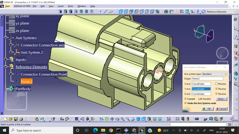
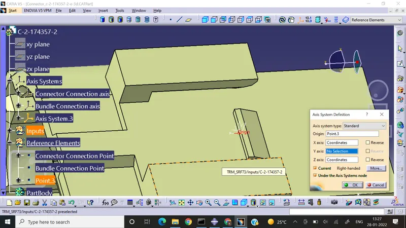
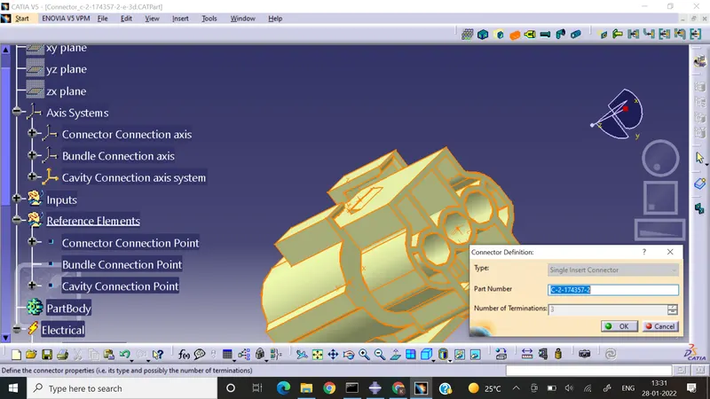
- Enter into electical part design workbench & define a connector with the given number of Terminals.
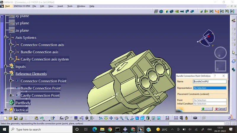
- Bundle Connection point definition
- Cavity connection Point Definition
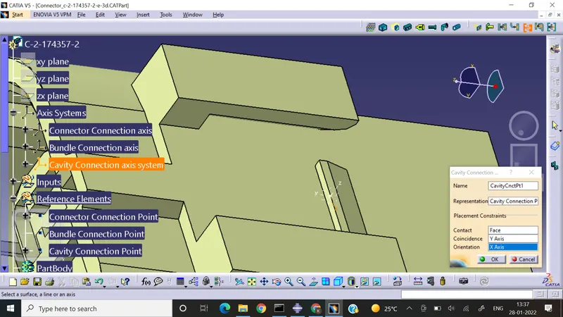
- Connector Connection point Definition
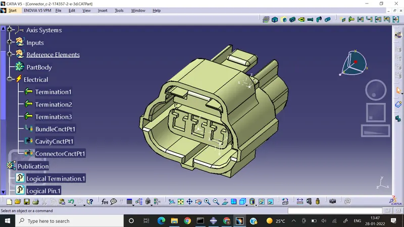
3. Connector Clip: Tyco 85229-1 : Connector Clip Mounting
- Cavity connection point
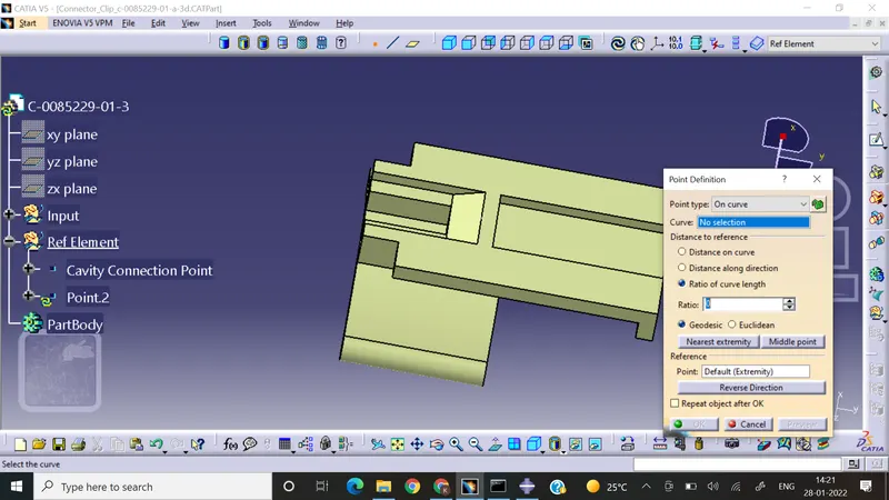
- Cavity Axis Definition
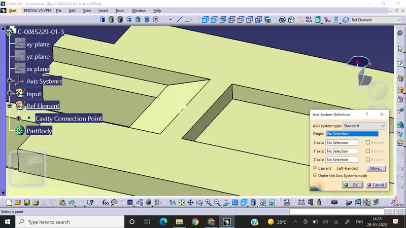
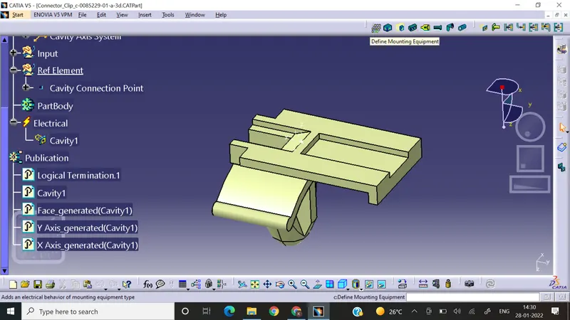
- After entering into the electrical part design we have to define the clip as mounting equipment
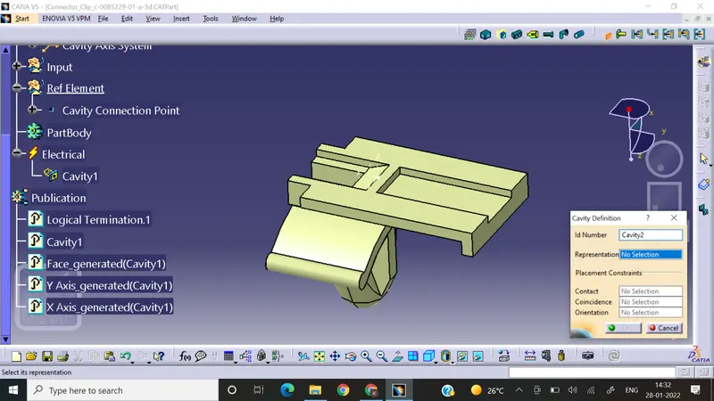
- Cavity Connection Defrinition: Define Cavity
Conclusion:
We can define the connector & connector mounting clip parts electrically using the part design & electrical part design workbenches. The reference entities used in defining the parts electrically are point & axis.