Wiring harness design in CATIA V5 - 3D modeling Week 2 Challlenge
EDS (Electrical Distribution System)
Electrical Distribution system deals with power distribution to the various components in an electrical system. It deals with Physical and Logical Architecture, Schematic Development along with wiring harness design, wiring harness component design of the same.
Logical Architecture mentioned above is the design of the system with details of logical connectivity between different system and sub systems. The Electrical Schematics is an extension of logical schematic which includes details like fusing distribution, grounding distribution, interconnects, wire properties to name a few.
Some Important Wiring Harness terms related to design engineer.
Wiring Harness Topology:
Before deciding the best route for wiring, it is necessary to determine how the harness will be divided among various components, for example, in an automobile the connection in a door has to be separated from the main body and the connections are made during the final assembly of the automobile. This is done to achieve the best Manufacturability, Serviceability and cost-effective design.
Wiring Harness Routing:
This part deals with finding the best path for the wiring harness for the given data by using set design rules and practices present in the industries.
Wiring Harness Packaging:
It is the final stage of the wiring harness design procedure and consists of best ways to fix the wiring inside the commodity in such a way that it is manufacturable, serviceable and most importantly, safe.
Design Flow of EDS
It consists of the two parts, electrical and mechanical part to make the harness design,
The electrical part of the design consists of
Logical Architecture: it is the logical connectivity between different system used in vehicles.
Electrical Schematic: this a more detailed version of logical architecture which has the necessary design rules required to developed the schematic.
The mechanical part of the of the design has it’s first step as physical architecture, which consists of gathering of data of all components that are needed from the front end of the car to the tip of the back side.
Next step is to work on the wiring harness routing packaging which is done virtually.After finalization, Harness drawings are made based on the mechanical and electrical input.
The main step of designing the wiring harness is done in the following manner:
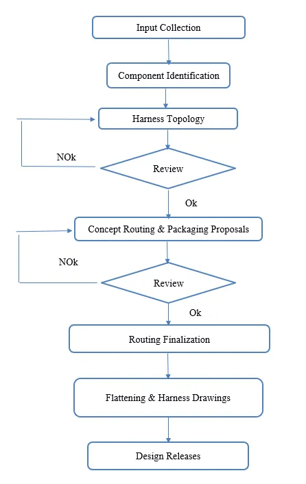
- Input collection: the relevant 3D data of the vehicle is needed to identify the required components of the wiring harness system.
- Component Identification: The components in the EDS and its details along with where it is placed in the vehicle is identified.
- Harness Topology: As discussed before it is the splitting of the harness in pieces for better manufacturing and serviceability. It is reviewed by senior engineers, manufacturing teams for producibility of the design, only after it is approved does the design process move forward.
- Concept Routing and Packaging Proposals: Wiring harness path definitions, mounting proposals, channel proposals, connectors parking etc. is again reviewed by the CFT team along with body, plastic powertrain design teams for the manufacturability and serviceability. it is necessary to design the system for DFA (Design for Assembly) and DFS (Design for Service).
- Routing Finalization: Detailing of the finalized concept.
- Flattening and Harness Drawings: The design needs to be flattened for producing of the final drawing that is sent to the manufacturing team.
- Design Releasees: sending the drawing to the next team for further production.
The wiring harness assembly consists of the following components –
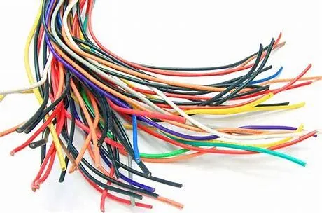
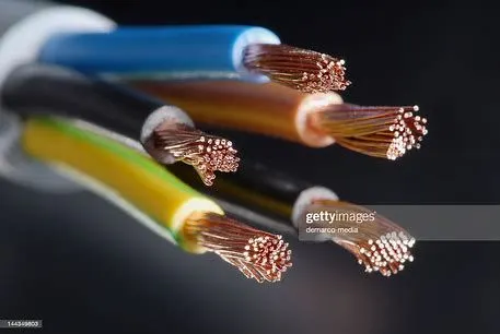
- Wires: Wires carry electric signal to various parts of the system, which is needed to start the engine, lights, meters, etc. of the automobile. It consists of various bundled wires with every wire responsible for transferring electric signals. They are usually copper wires covered with plastic coating for protection purposes. These days aluminum is also used do to it being light weight.
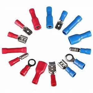
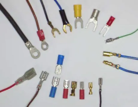
- Terminals: Terminals are used to make secure electrical connection. They are metal conductor with plating in various shape. Terminals come in various shapes; the best fit is determined by the application for which it is utilized. Types include ring, spade, hook bullet, etc. It is also insulated or non-insulated depending in the manufacturer.
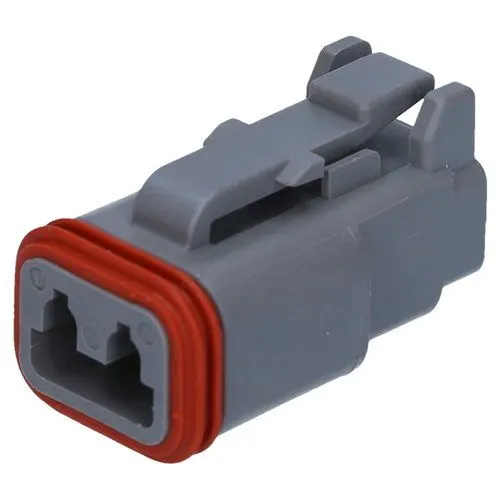
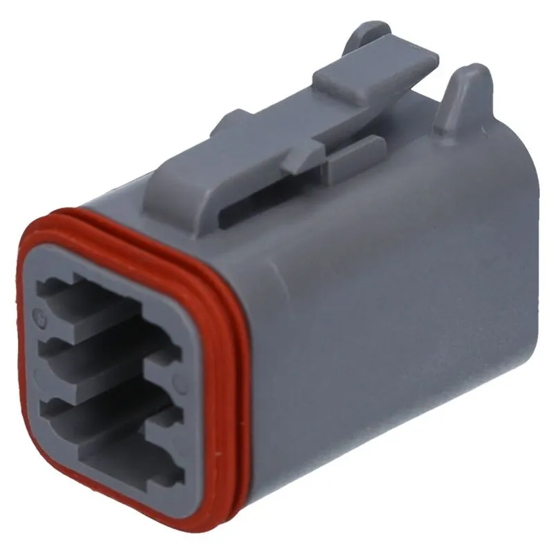
- Connectors: it is an electro-mechanical device made of plastic with locking and retention features. It is used to make an electrical and mechanical connection between harness and components.
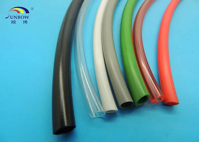
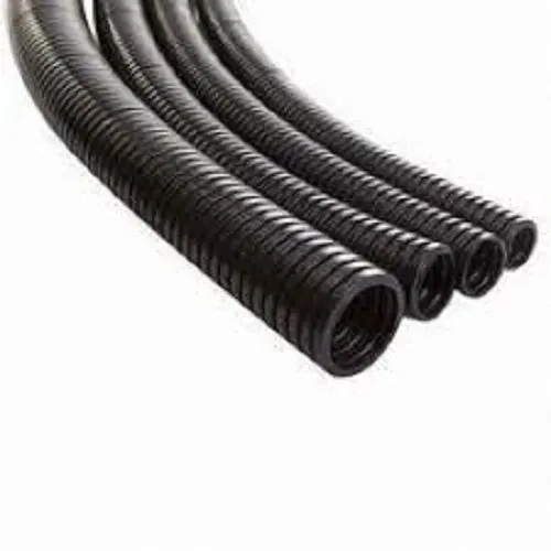
- Protection Coverings: These are corrugated tubes also called as cot tubes and has wide range of application I the automobile industry. They are made of plastic and are very flexible in nature. Different types of tube have different properties like Temperature resistance, wear resistance etc., depending on the area it is used in.
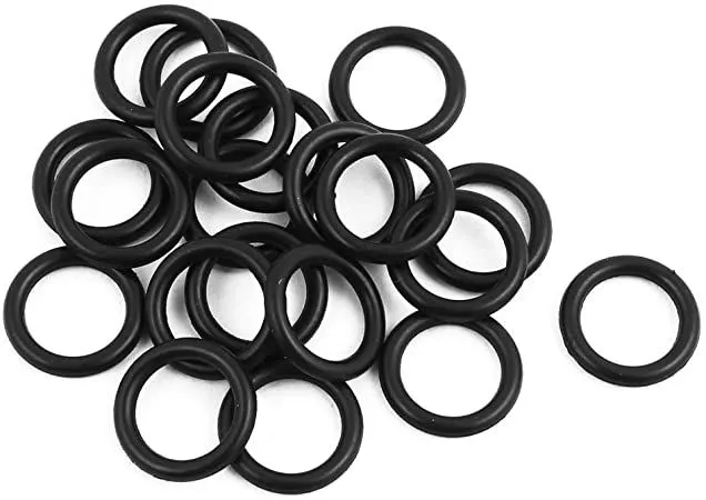
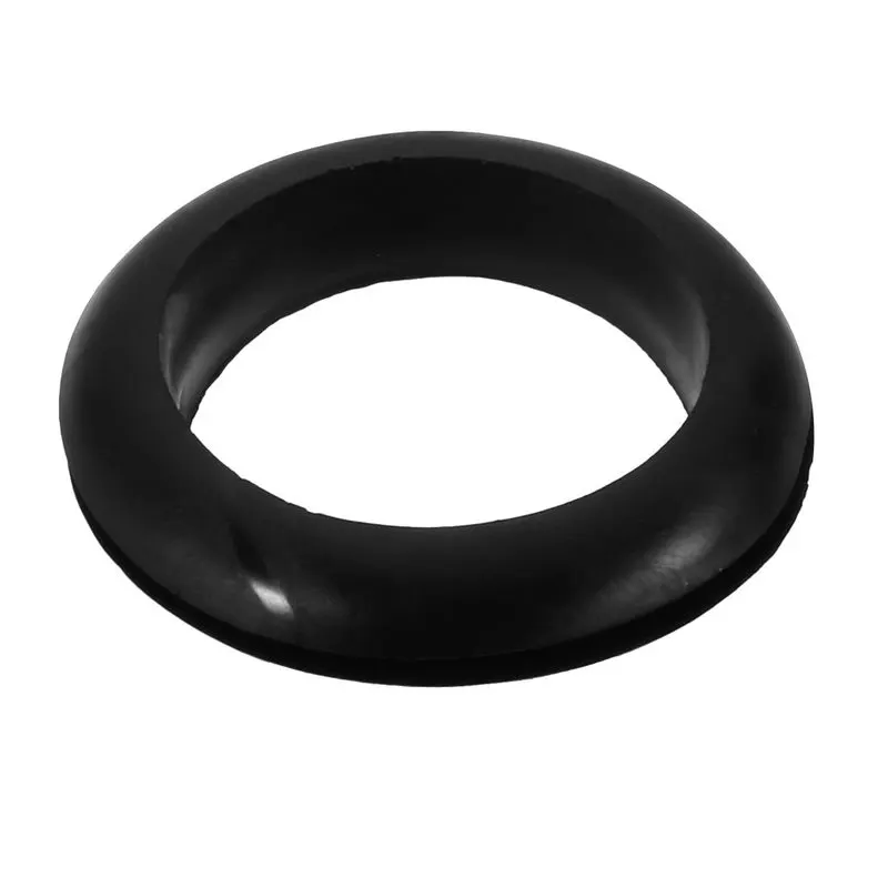
- Sealing Grommets: these are made of rubber and used of sealing, protection and absorption of shocks. Sealing is needed when the wires pass from dry zone to wet zone in the wire harness design.
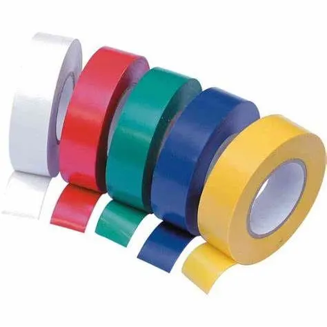
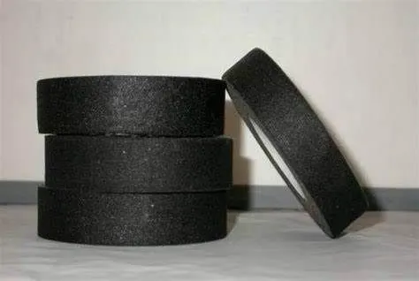
- Insulations: these are special types of tapes made of PVC or cotton/ Polymer material. Its purpose is to align the wiring harness in a systematic manner. Cotton types are used for areas where high temperature resistance is needed.
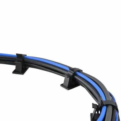
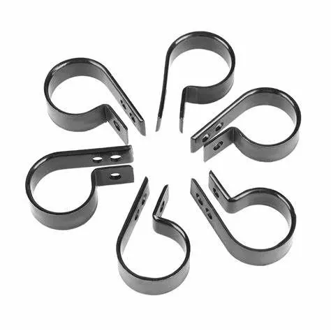
- Clips and clamps: These are used to securely clamp the harness to various parts of the vehicles. It is also made of plastic and has mounting features provided.
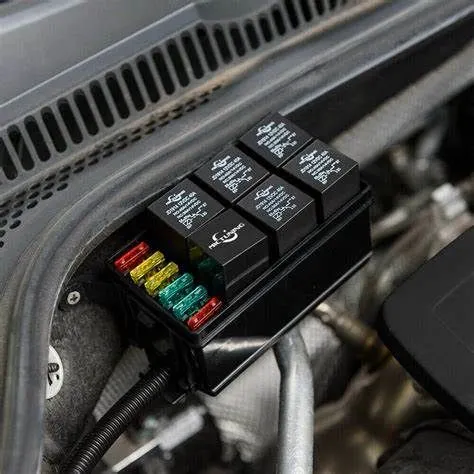
- Fuse and relay box: these are again plastic components used to systematically contain the fuse and relay and are designed so that they are physically and environments safe from damage. The selection of fuse and relay box depends on the number of fuse and relays required in a system.
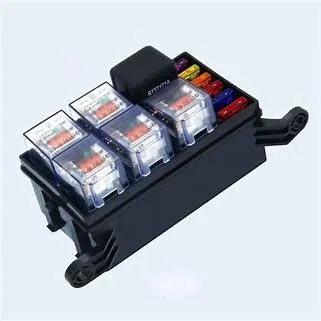
- Retention Devices: these are mounting devices for connectors and other harness components. It consists of mounting clips, back shells, secondary locks. Mounting clips are provided for protection from vibration of the component during running conditions of the vehicle. The secondary lock is provided in addition to the primary locking between the terminals to ensure there is no failure due to terminals back-outs. Back shells are used to guide the wire where area is restricted, it is used for smooth flow of the wires.
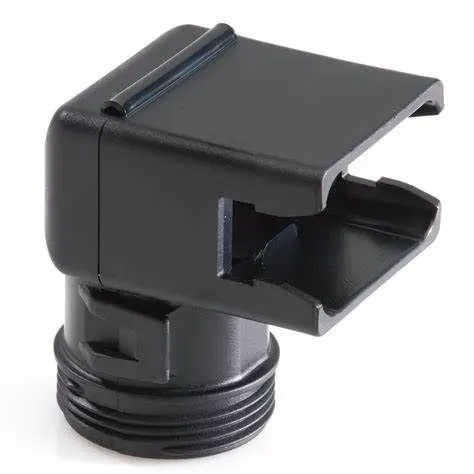
Backshell
- Guiding Channels: It is a plastic part of metal part designed to guide harness bundle in given geometric area to secure and protect harness. It is done In the areas the wire harness is visible and the aesthetics need to be maintained. These are usually customized depending on the area.
- Electronic components: Other components like terminating resistor, diodes, timers etc.
Defining a component as an electrical part:
To define the part as electrical, following steps should be performed in CATIA:
1. Downloading the component, or creating the component, in this case a connector.
2. Geometrical Parameters: Points and axis system needs to be created for the various connection points on the component.
3. Define Component: Then we move on to the eletrical part design workbench to define the part as electrical, without this, the connection points cannot be defined.
4. Define Bundle connection point: Defines where the harness bundle will enter from in the given point.
5. Define Connector connection point
6. Define Cavity connection point: It is optional as the connector may or may not have a clip.
By defining the above given points the part is electrically defined and can be added to the catalogue to be used whenever required.
Following are the defined components of the given connecters and clip.
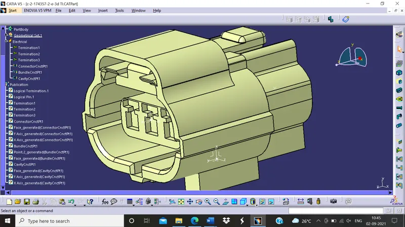
C-2-174357-2 (Connector)
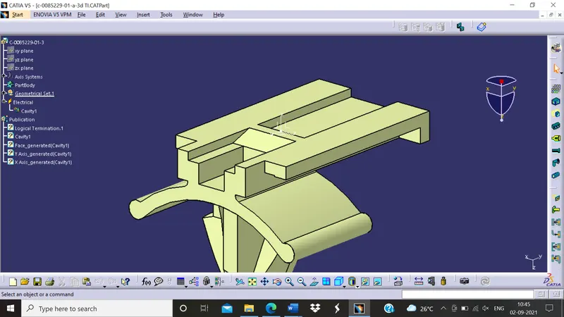
C-0085229-01-3 (Connection Clip)
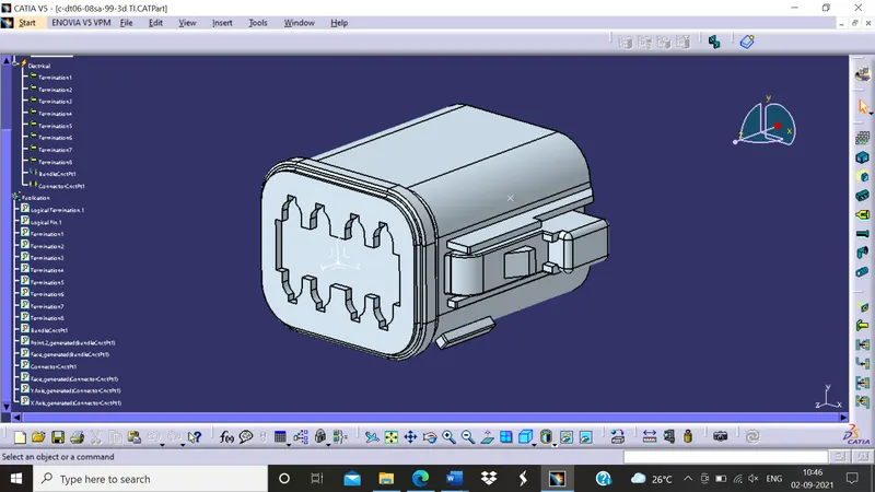
C-DT06-08SA (Connector)