Wiring harness design in CATIA V5 - 3D modeling Week 2 Challenge
1. Deutsch DT06-08SA
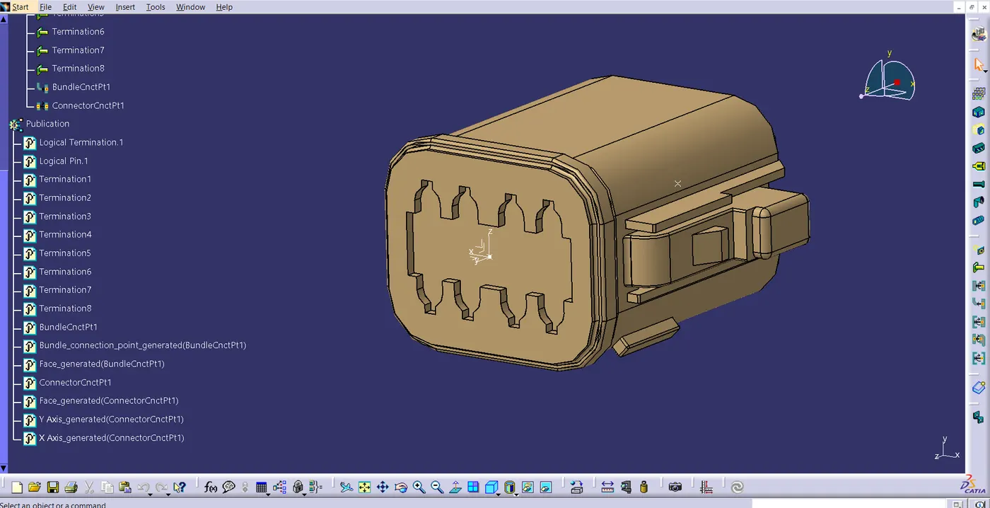
- First uploading of the connector occurs in the part design work bench.
- We define the bundle and connector connectivity points.
- On the cavity and connector connection points are the axis systems positioned.
- The axis system's orientation is not specific; all the parts must follow a similar orientation.
- X-Axis in the direction of lock, Z-axis in the direction of bottom to top, and Y-axis in the direction of the connection.
- Now, using the number of terminals, we define this part as an electrical element/connector.
- The electrical part design workbench defines connector and bundle connection.
2. Tyco 174357-2 and 85229-1
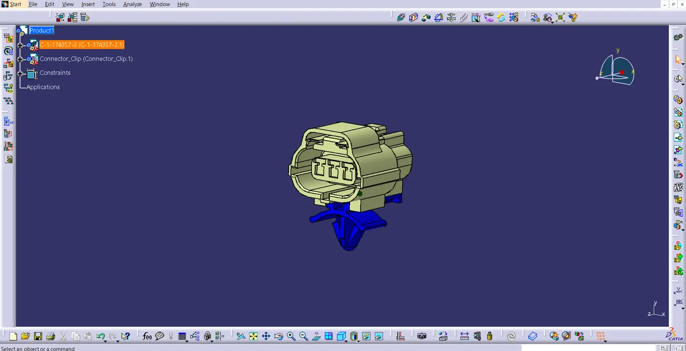
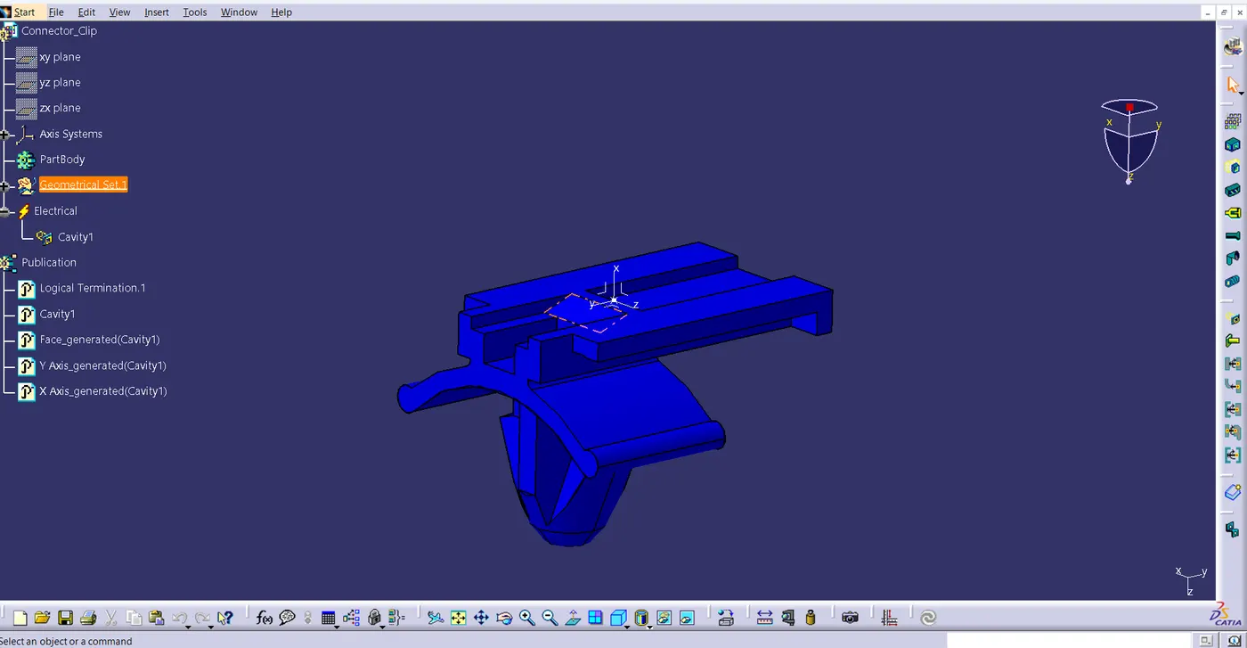
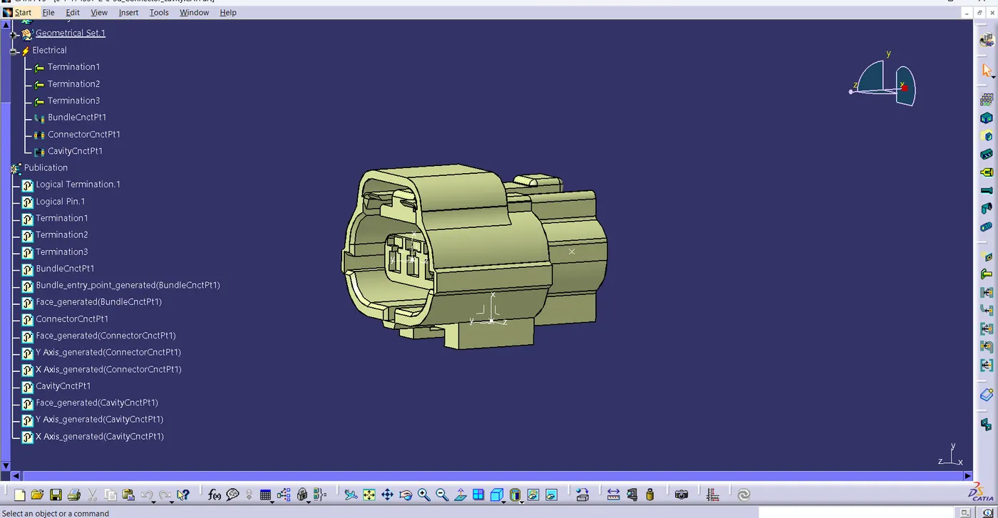
- The second connector was maintained using the same procedure. The connector-cavity connection point must be included here. This is done to fix the connector's clip on.
- The clip in the electrical part design workbench must be defined as the cavity.