Wiring harness design in CATIA V5 - 3D modeling Week 2 Challenge
WIRING HARNESS DESIGN IN CATIA V5-3D MODELLING WEEK 2 CHALLENGE:
AIM:
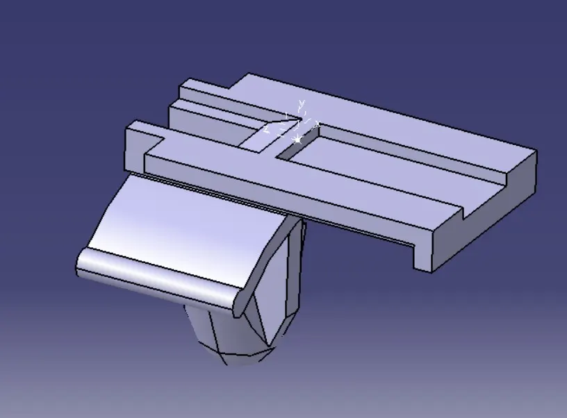
To define above given connector and clips with geometry creation and assemble in the electrical assembly work bench.
INTRODUCTION:
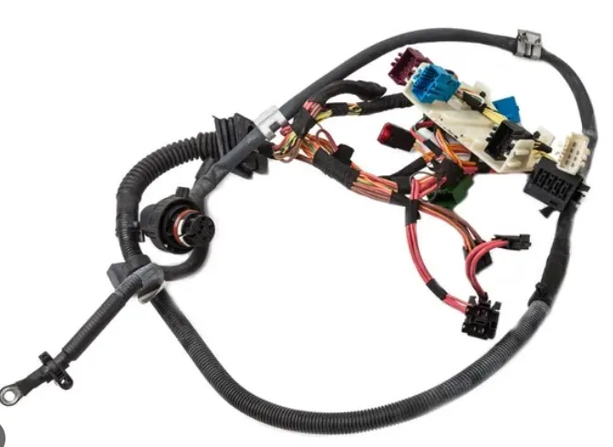
- Wiring harness design is a process that organize and align the electrical hardware for the passing the electricity through the automotive system.
- It contain the Electrical Distribution system (EDS),Electrical assembly,E&E Architecture,Logical schematics,Electrical schematic,Wiring harness topology,wiring harness routing,wiring harness packaging.
- In this challenge we are using connectors and clips it is involved in wiring harness system.
CONNECTOR:
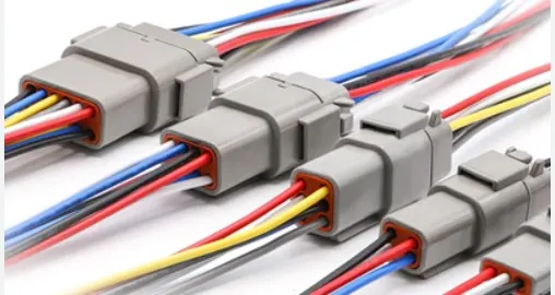
- An electrical connectors,is an electro mechanical device used to join electrical termination and create an electrical circuits.Electrical connectors consist of housing ,terminals,wedge lock seals,cavity,mounting cam etc....
- it contains plastic molded housing with locking & retention features.
CLIPS & CLAMPS:
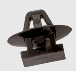
- It is a plastic molded parts with mounting & snaping features.
DEFINITION OF CONNECTOR:
1.CREATE OR DOWNLODE CONNECTOR:
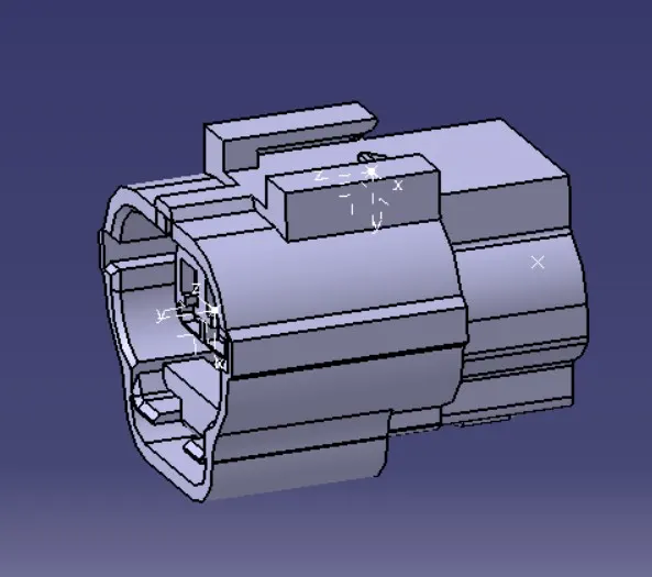
- First we need to downlode connector from the TE website as a Step or Igs file
2.CREATE REQUIRED GEOMETRICAL PARAMETERS:
- For that we need to decide connector connecting point and bundle connecting point.
- Then we need to create point and axis at the connector connecting point.
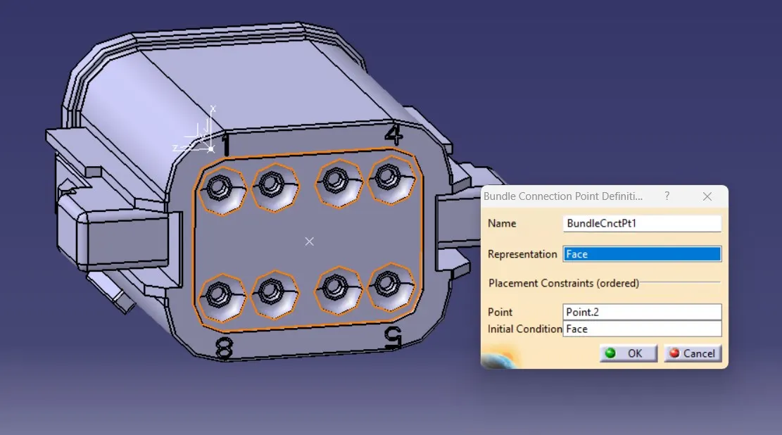
- Then we need to create point at bundle connecting point.
- These process are done in part design workbench.
3.DEFINE PART AS CONNECTOR:
- Then we need to move to electrical design work bench.
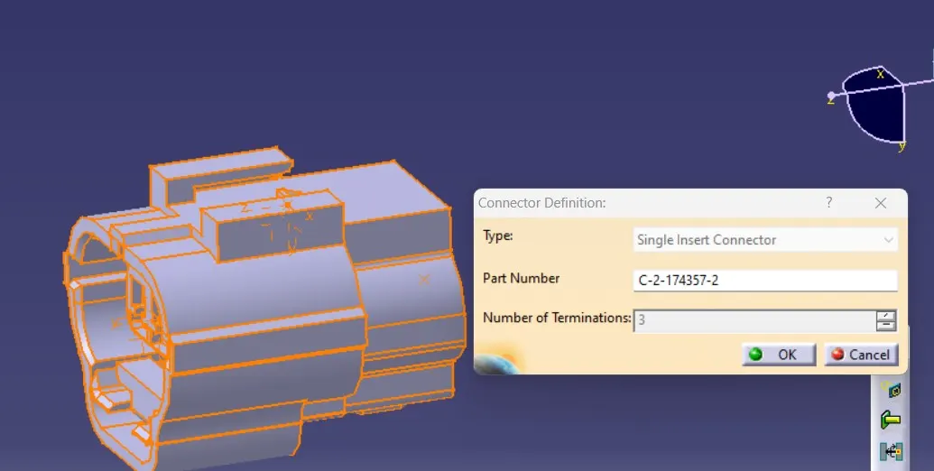
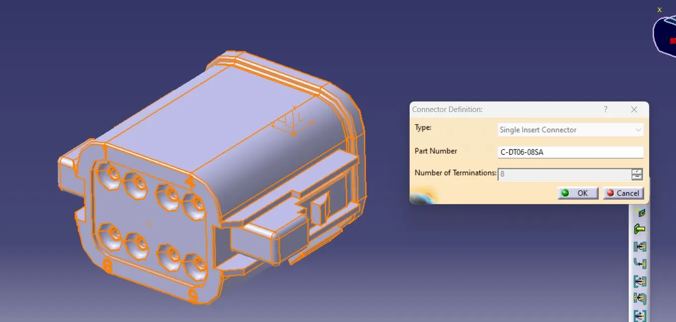
- Then we need to select the define connector icon and select the part as a connector in single electrical mode.
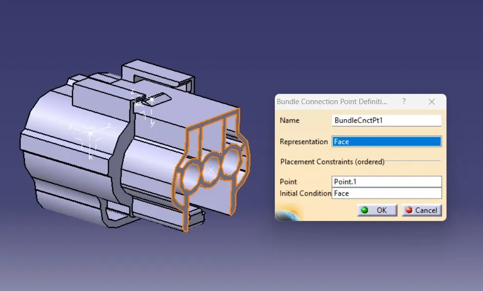
4.DEFINE BUNDLE CONNECTION POINT:
- For this we need to select define bundle connection point icon.
- Then we need to select the entry point and bundle butting face.
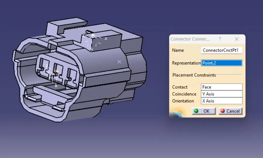
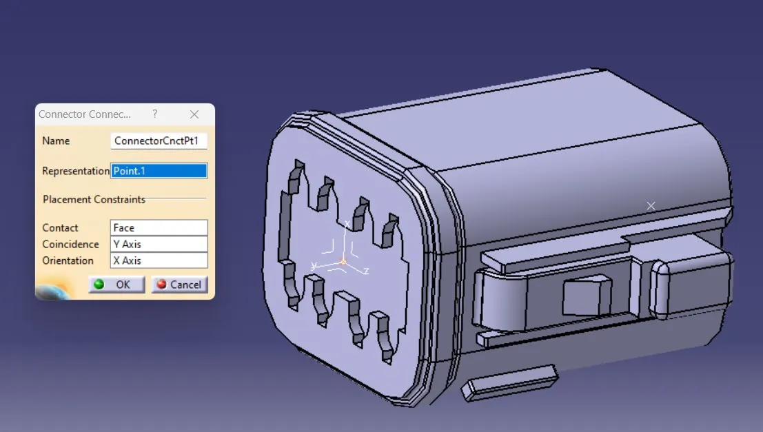
5.DEFINE CONNECTOR CONNECTION POINT:
- For this we need to select the connector connection point icon
- Here we need to select the base reference point,referance face ,coincide axis and orientation axis.
- For coinside axis we need to select the Y axis of the connector and for orientation axis we need to select the X axis.
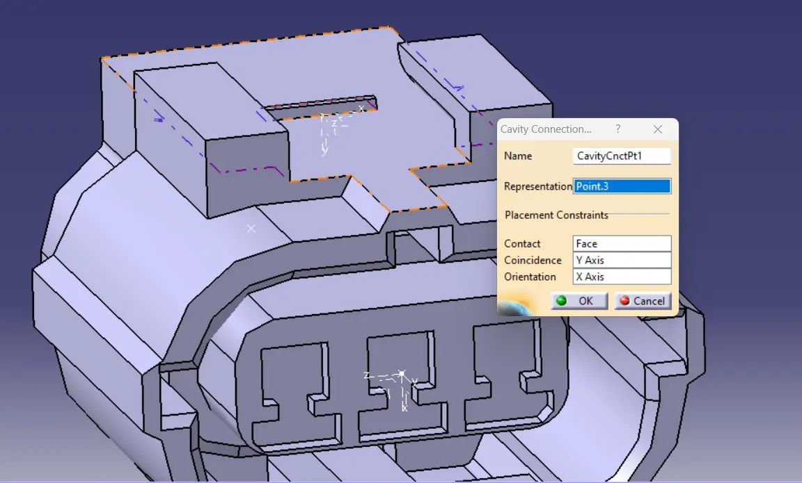
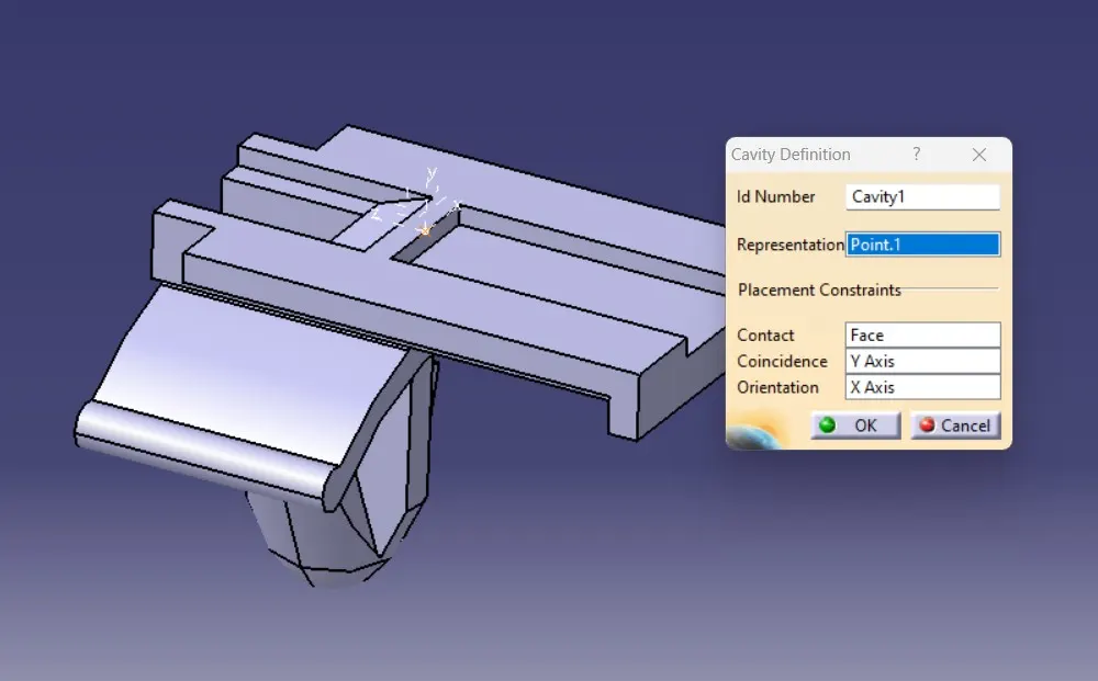
6.DEFINE CAVITY CONNECTION POINT:
- For this we need to select cavity connection point or cavity Icon.
- In this operation we need to create the mounting point.
- And select that mounting point and the mounting face in the connector.
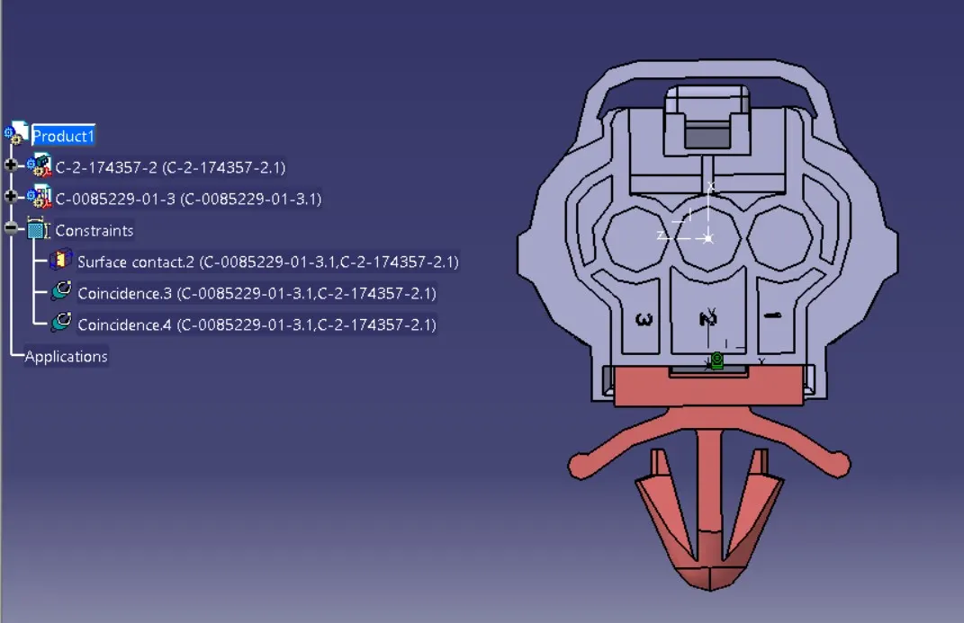
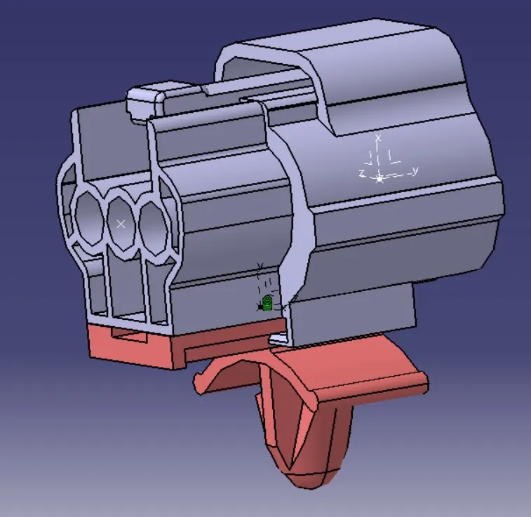
ELECTRICAL PART ASSEMBLY:
- Using connect and disconnect icon ,we are assembled the connector and clip together in geometrical manner.
CATALOGE CREATION:
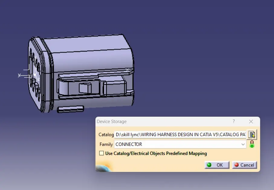
CATALOGE CREATION FOR CONNECTOR AND STORING:
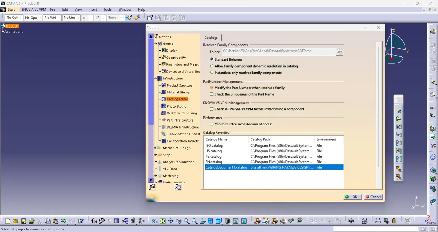
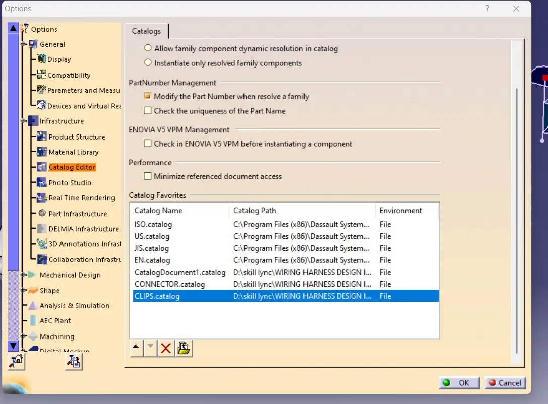
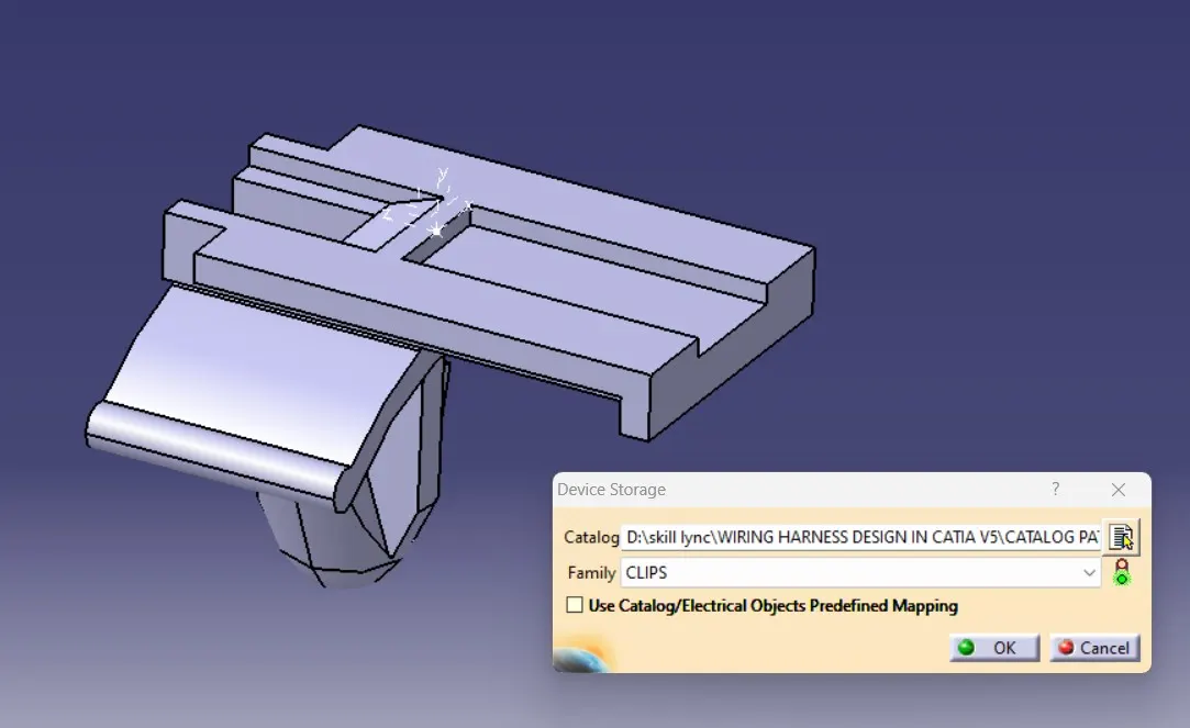
CATALOGE CREATION FOR CLIP:
CONCLUSION:
- By this challenge we are learned about the connector & clamp definitions and Electrical part assembly.
- Then we are learned downloading the files form the te.com website and then defining the parts electrically and creating a catalogue for the components.