Wiring harness design in CATIA V5 - 3D modeling Week 2 Challenge
CONNECTOR DEFINITIONS IN CATIA V5
Deutsch DT06 – 08SA
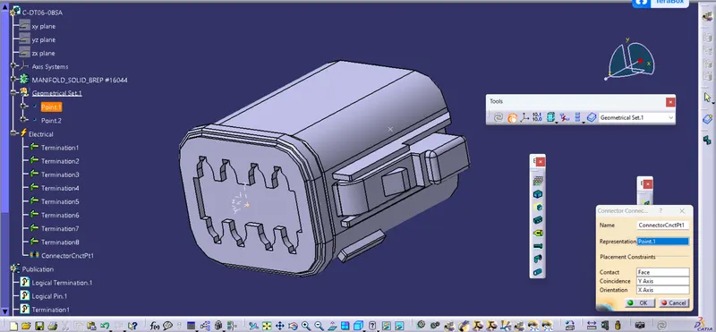
Connector connection point:
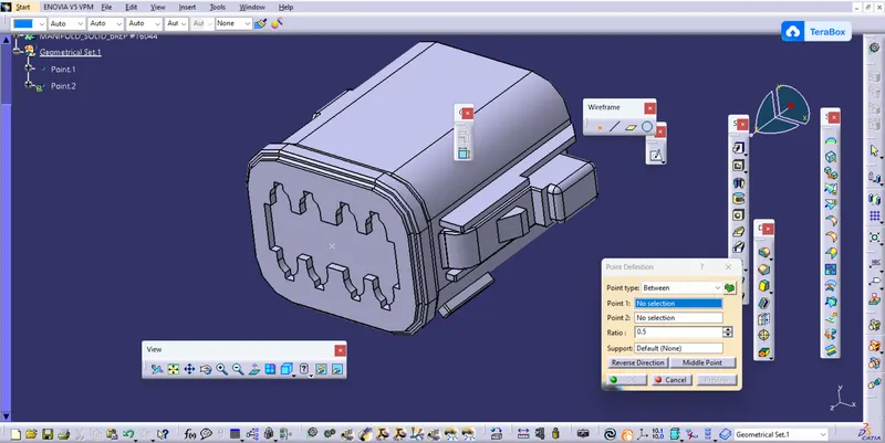
Create midpoint on the contact face which will be normal to wire bunddle insertion.
Create Axis System with respect to the point which we have created and defining the axis direction as shown below,
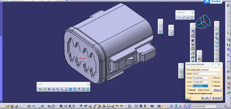
Y Axis should be facing towards the face of the connector
Switch to 'Electric Part Design'
Define the part as connector in catia, give no. of termination as 8 because we have 8 entry points for wire.
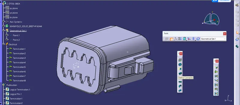
Define connector connection point
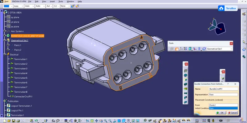
Define Bundle connection point
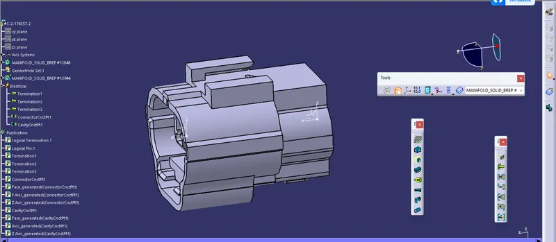
2.Tyco 174357-2 :
- Create midpoint
- create Connector connection point
- create Connector connection axis system
- create cavity connection point
- create cavity connection axis system
- Switch to Electric part design and define part as connector
- Define Connector connection point and cavity connection point
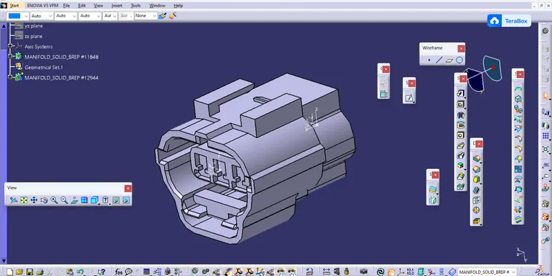
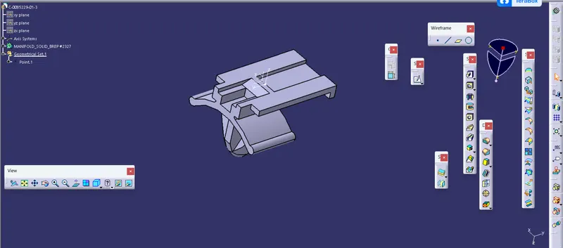
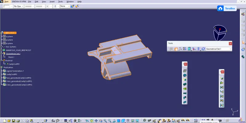
3. Tyco 85229-1 :
- Create midpoint
- create cavity connection point
- create cavity connection axis system and orientation should be same as in connector
- Switch to Electric part design and define part as Mounting Equipment
- Define cavity connection point