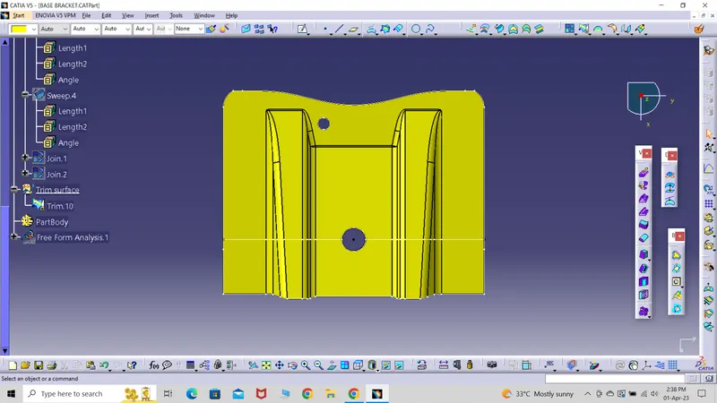
Week 9 - Challenge 1 - Base Bracket Design
Creation of a part from the given Class A surface is done by creating 2 surfaces that are B surface and C surface.
Class A is the surface that is created by the concept sketches made by free hand sketchers. The finalised sketch is then fed to the computer and a 2D surface is created out of it by the use of a software like Alias. This computerized design is known as Class A surface.
Class B is a reference surface that is created by the design engineer and is a copy of the class A surface that is at a distance equal to the thickness of the part.
Class C is again a reference surface that is created by the design engineer to connect Class A and Class B surface also known as the side wall of the surface.
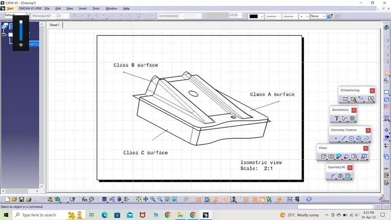
The technique that is used to create the model is to initially create a class B surface at a distance equal to thickness(2.5mm here) and later a vertical surface class C. Then trim the three surfaces to obtain the required part.
->) Steps involved in the creation of the aforementioned part
*) The first task to begin the model with was to create the tooling axis. The model was observed from all the 3 planes and xy plane was selected to create the part and so the hole was taken into consideration and a point was created.
*) The same point was taken as reference and a dummy tooling line was created. This line was later used to create a plane to obtain the intersection pattern.
*) The two slopes on either side of the intersection was used to create two more lines and in the end a bisector line was created which became the main tooling axis.
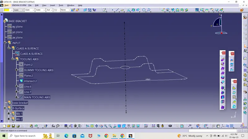
*) A geometrical set with the name base bracket was created and then the whole class A surface was separately extracted.
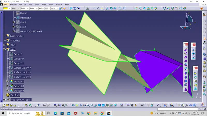
*) The same extracted surfaces were then untrimmed to get a complete surface and then extrapolated so that trim command could be successfully performed.
*) 2 sides at a time were trimmed to get the below surface which was offsetted to 2.5mm.
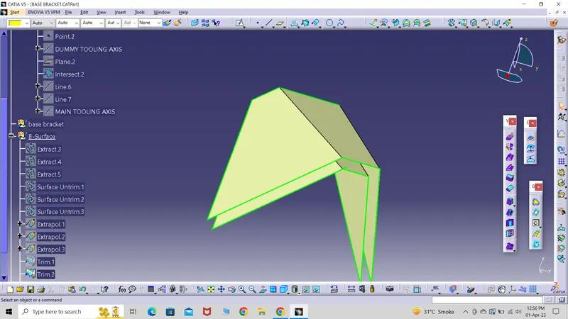
*) The same technique was used to create the other region which was identical to the first region as shown in the s.s.
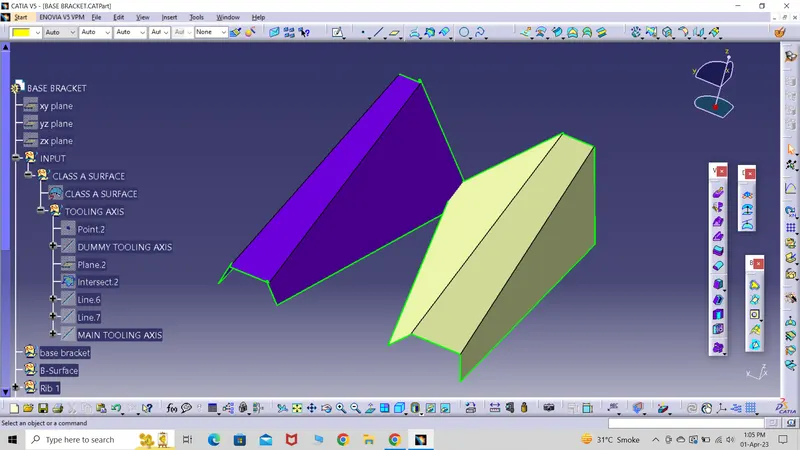
*) The central region was also extracted and offsetted to 2.5mm.
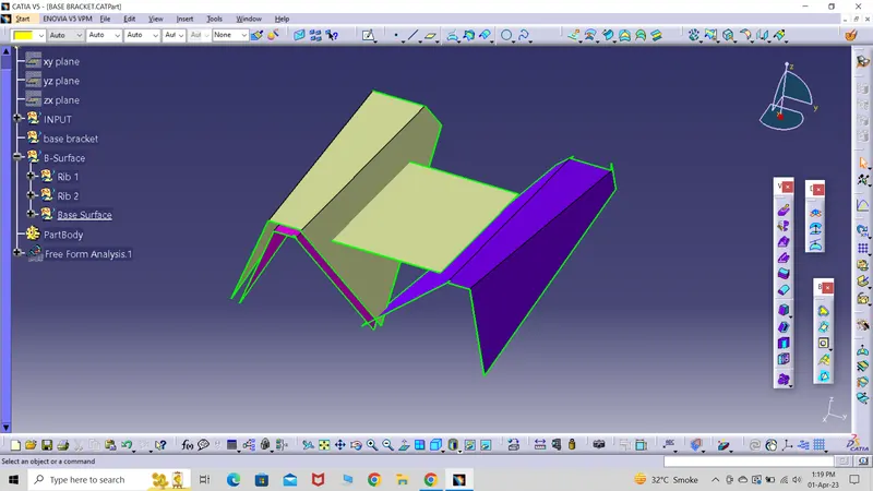
*) The same region was used to trim with the aforementioned two patterns that were created earlier to obtain the required surface.
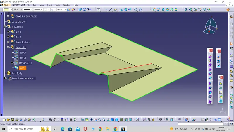
*) The surface B created is the exact copy of class A but at a distance of 2.5mm and without fillets so fillets with a value of radius+thickness of the part i.e. 3+2.5=5.5mm was given.
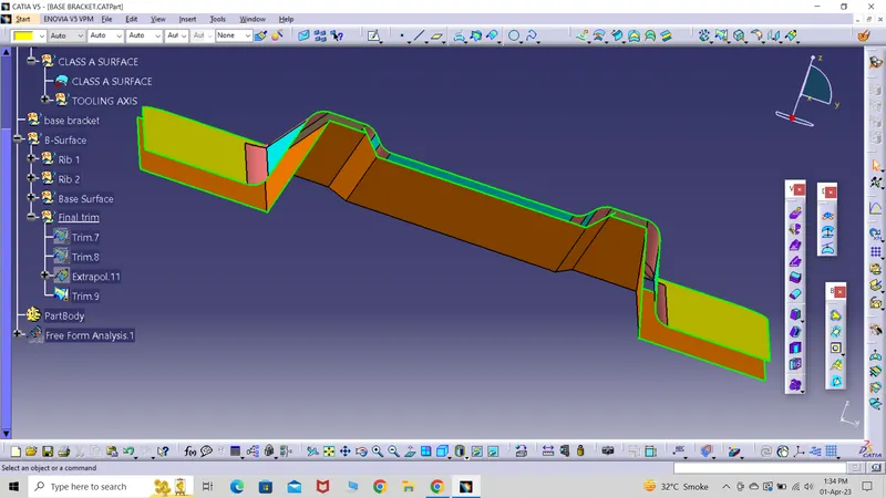
*) It surrounding region of the class was also extracted and extrapolated to trim the surface B with it.
*) The final surface created is shown below and is surface B.
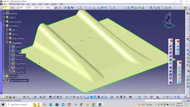
*) The boundary was created by considering class A.
*) Sweep command was used and for reference, main tooling axis and also the direction of the tooling were considered to create class C surface.
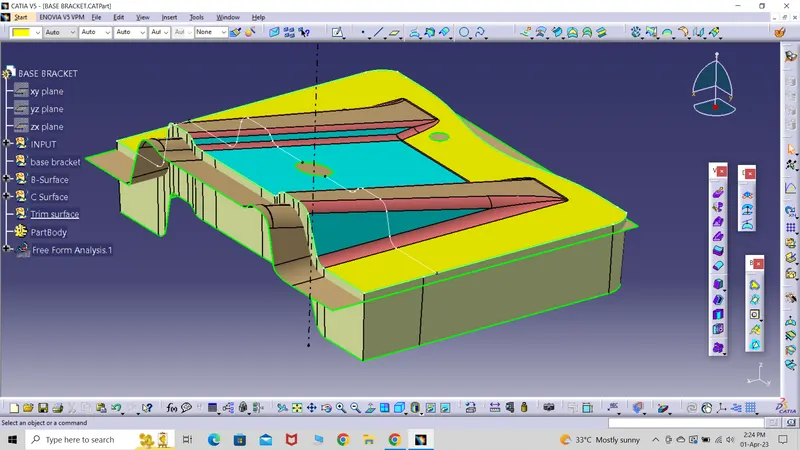
*) In the same manner, the two holes on the sheet were also swept by creating the boundaries and later sweeping them both simultaneously.
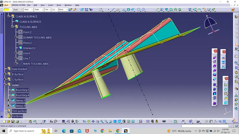
*) The required 3 surfaces were joined together taking holes into consideration too.
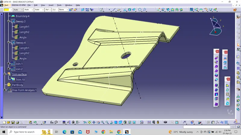
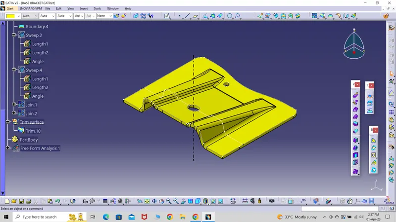
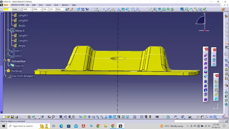
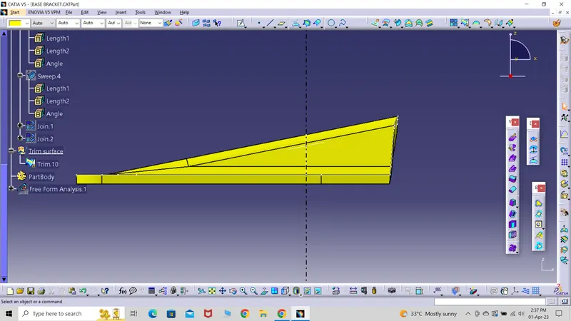
*) All the three surfaces were lastly trimmed to get the final part which is shown below.
DRAFT ANALYSIS
In plastic design, the draft analysis or angle that is considered in the OEMs is 3 degree.
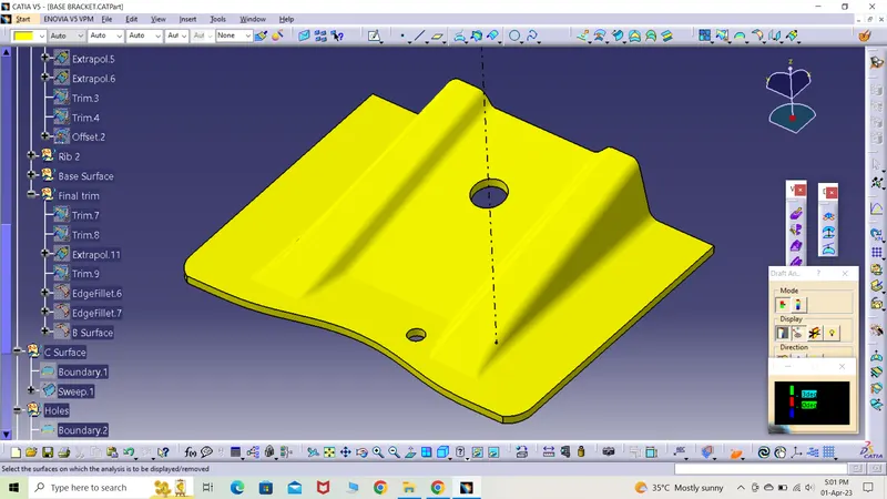
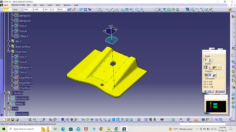
*) First thing to carry out was to select the compass and set it on the tooling axis in upward direction.
*) By clicking on the surface, the whole part turned into green color. If blue was visible that meant that the analysis was inversely done so just by flipping the direction, draft analysis
*) The hollow part was later created into a solid body by going the part body option and then selecting close body surface.
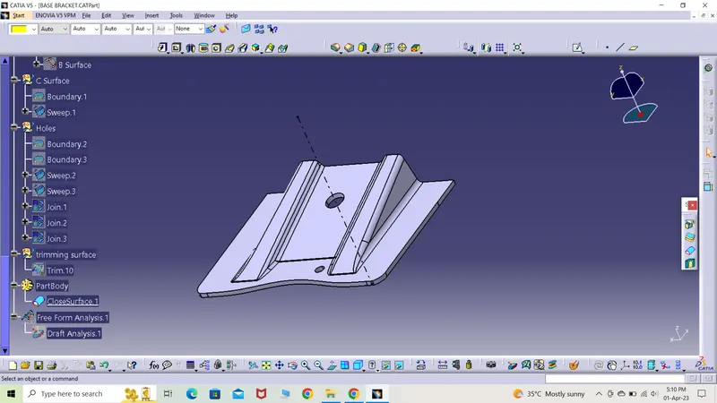
*) Draft analysis on the solid part resulted in green, blue regions.
*) The green region shows the part which is toolable or produceable by the molding machine and the draft angle is 3degree.
*) Blue color region states that the part can be allowed in some OEMs but still need to be improved for the other OEMs as the draft angle is more than 3 degrees.
*) Red color which is not there in this case states that the draft angle is less than 3 degree and cannot be produced or if produced would be faulty.
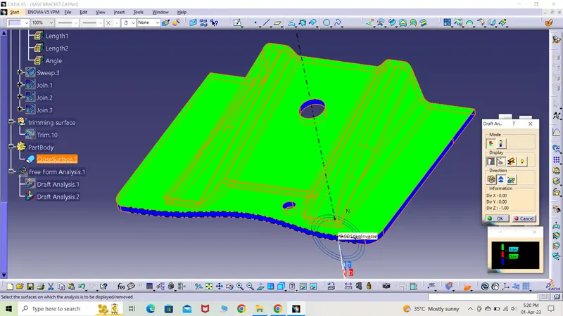
ISOMETRIC VIEW
FRONT VIEW
SIDE VIEW
TOP VIEW