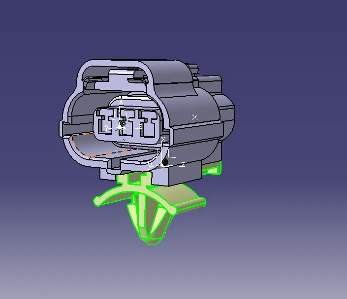
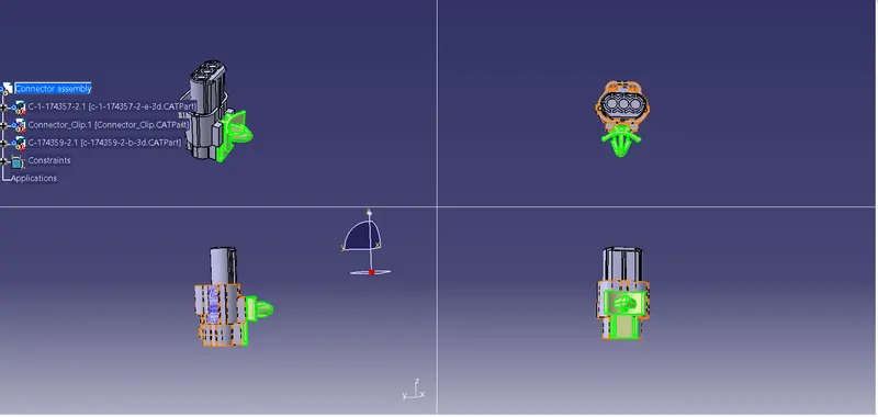
Wiring harness design in CATIA V5 - 3D modeling Week 2 Challenge
Report on Wiring Harnes:-
The wiring harness system in the automobile industry is a critical component that plays a central role in the electrical and electronic infrastructure of modern vehicles. It consists of a network of interconnected wires, cables, and connectors, carefully organized and bundled together to transmit electrical signals and power between various components of the vehicle. This system ensures efficient and reliable communication between the numerous electrical devices and systems within the automobile.
Key Components of Wiring Harness System:
-
Wires and Cables: The primary building blocks of a wiring harness are electrical wires and cables. These are made of copper or aluminum, insulated with materials like PVC, cross-linked polyethylene (XLPE), or polyurethane to protect against damage and ensure proper signal transmission.
-
Connectors: Wiring harnesses use a variety of connectors to join different components together. These connectors come in various shapes and sizes, and they facilitate secure and reliable connections while also allowing for easy assembly and disassembly during manufacturing, maintenance, and repairs.
-
Terminals and Pins: Terminals and pins are used within the connectors to establish contact with the wires and cables. They ensure a stable and low-resistance connection, preventing electrical issues like voltage drops and signal interference.
-
Protective Sleeves and Tapes: To shield the wiring from environmental factors such as heat, moisture, and abrasion, protective sleeves and tapes are used. These materials provide insulation, protect against physical damage, and maintain the integrity of the harness over its lifetime.
Wiring Harness Manufacturing Process:
The production of wiring harnesses is a complex process involving several stages:
-
Design and Planning: Engineers and designers create a detailed blueprint of the wiring harness based on the vehicle's electrical requirements. Factors like component locations, wire lengths, connector types, and insulation materials are considered during this phase.
-
Wire Cutting and Stripping: Large spools of wire are cut into specific lengths, and their ends are stripped of insulation to expose the conductor. Automated machines are often used to ensure precision and speed during this step.
-
Crimping and Terminal Assembly: The stripped ends of wires are fitted with terminals and pins through a process called crimping. This establishes a secure and reliable connection between the wire and the connector.
-
Connector Assembly: Wires with crimped terminals are then connected to their respective connectors, and the assembly is carefully organized to match the design specifications.
-
Bundling and Taping: The interconnected wires are bundled together, and protective sleeves or tapes are applied to the harness to keep the wires organized and shielded from external elements.
-
Testing and Quality Control: The completed wiring harness undergoes rigorous testing to ensure all connections are intact and functional. Quality control checks are performed to identify and rectify any defects.
Significance of Wiring Harness System:
The wiring harness system is of paramount importance in the automobile industry for several reasons:
-
Improved Efficiency: It streamlines the electrical connections, reducing the complexity of the vehicle's electrical architecture, which, in turn, improves the efficiency of the electrical systems.
-
Enhanced Safety: Properly organized and insulated wiring harnesses minimize the risk of short circuits, electrical fires, and accidents due to electrical malfunctions.
-
Time and Cost Savings: Pre-assembled wiring harnesses simplify the vehicle assembly process, reducing production time and costs.
-
Easy Maintenance and Repair: Modular wiring harness systems make it easier to identify and replace faulty components, reducing downtime during maintenance and repair work.
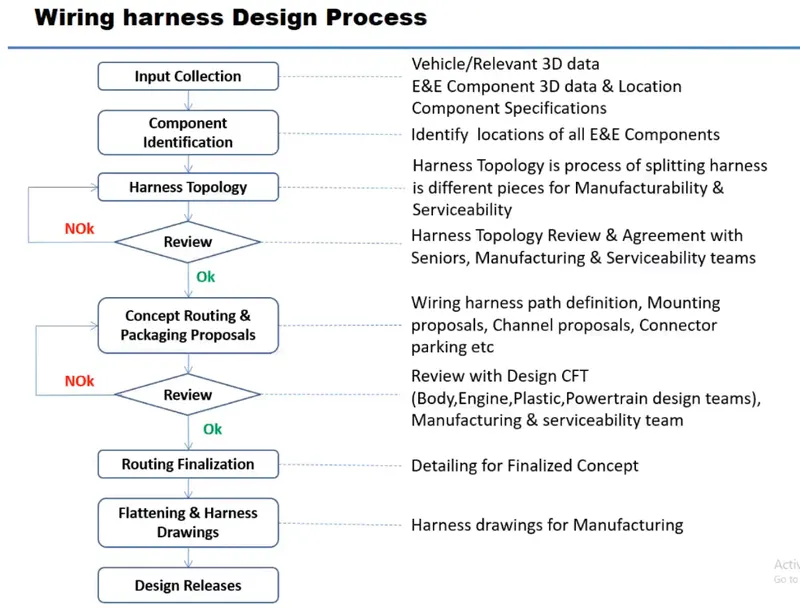
Wiring Harness Design Process:-
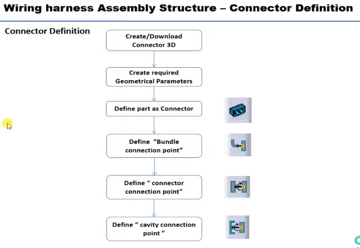
Wiring Harness Assembly Structure- Connector Defination:-
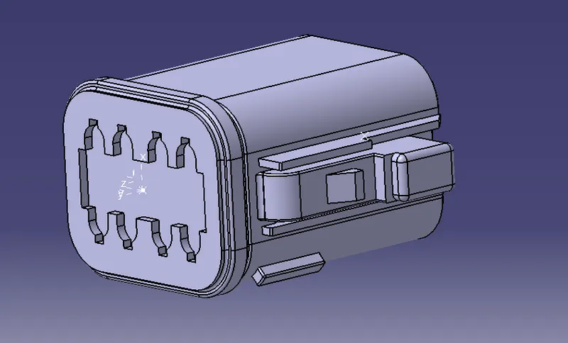
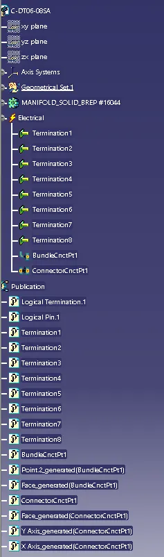
1. Deutsch DT06-08SA:-
Strp 1:-
Defining geometrical properties (points and axis system)"Under Mechanical part workbench"
Bundle entry side point -
Selecting two random points diagonally to get a center point, under point type "between".
Mating side point -
Selecting two random points diagonally to get a center point, under point type "between".
Mating side axis system -
Creating an axis system concerning the center point as the origin of the axis. The Y axis is directed at the mating direction, the X axis is directed towards the locking side and the Z axis is directed upwards.
Step 2:-
- Define part as a connector "Under Electric part workbench"
Defining part as an electrical connector under Electrical Part Design Workbench. Selecting the number terminations 8.
- Define bundle connection point (bundle/wire entry side)
Defining bundle connection point at the bundle entry side where, representation is the face, point as the center point, and initial condition also as the face.
- Define connector connection point (mating side)
Defining connector connection point at the mating side of the connector where representation is the center point, contact is the face, coincidence is the Y axis, and, orientation is the X axis.
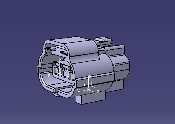
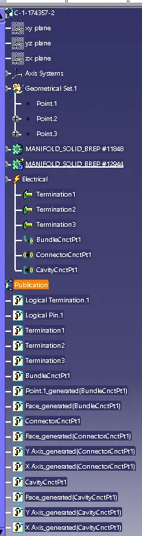
2. Tyco 174357-2:-
for Creating this part we will again repeat step 1 and step 2
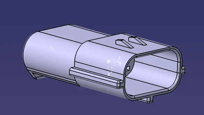
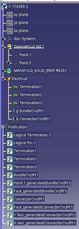
3. C-174359-2:-
4. Connecting_Clip:-
Connector Assembly:-