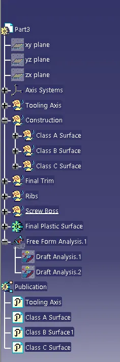
Week 10 - Challenge 1- Attachment Feature Creation (Ribs & Screw Boss)
Tooling axis:-
In order to generate the tooling axis, I utilized a process which involved extracting the surface of class A without any propagation. Following this, I proceeded to create a point at the exact center of the extracted surface, and subsequently established a line in the Y direction at that point. With the tooling axis now in place, I carried out a draft analysis on class A to assess its draft angle.
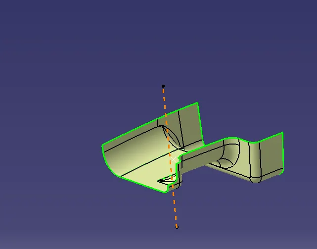
Draft Analysis for Class A Surface:-
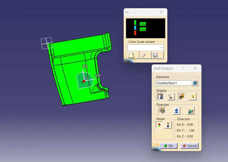
In order to carry out the draft analysis on class A, I utilized the featured draft analysis tool in the Generative shape design workbench. Initially, I selected the 'use of the compass to define the new current draft direction' command, which enabled me to align the compass with the tooling axis.
Once the compass was correctly aligned with the tooling axis, I then proceeded to select the surface of class A for which the draft analysis was to be performed. The surface was highlighted in green, in accordance with the colour bar angle and colours that had been defined for this purpose. Specifically, I designated green for draft angles greater than 0.9 degrees, red for angles less than 0 degrees, and cyan for angles between 0 and 0.9 degrees.
I observed that some faces were not getting cleared when I set a draft angle of 3 degrees. Therefore, I gradually reduced the draft angle until every face had been successfully cleared.
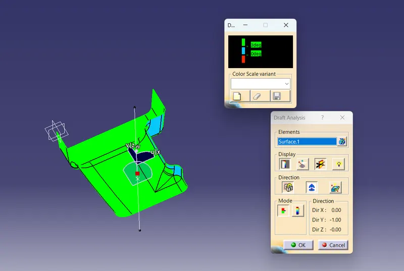
To clear the faces which are not cleared with a 3deg draft angle, I gave a 0.9deg draft angle to clear every face.
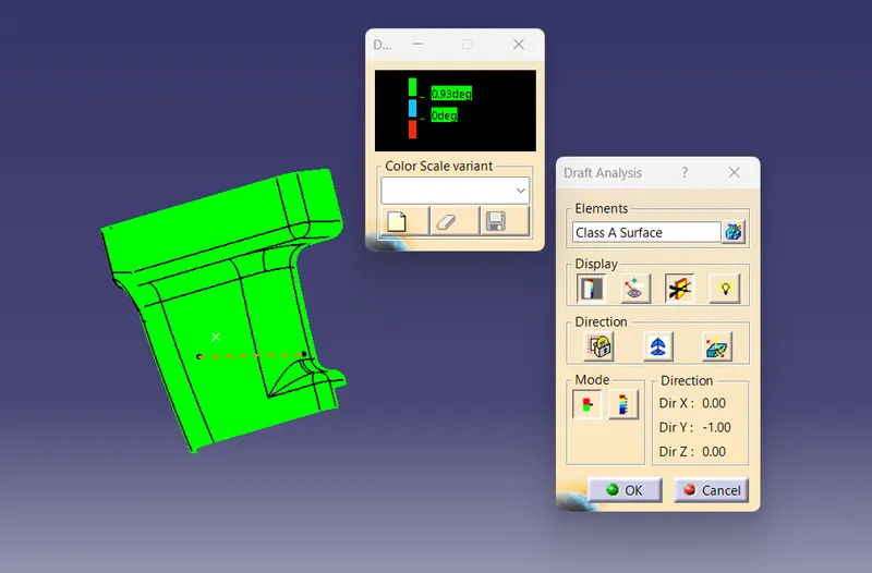
The draft angle is 0.9deg:
Class B Surface:-
In order to generate the class B surface for the door handle, I offset the class A surface by 2.5mm inward. Upon creating the offset surface, it became apparent that some patches had formed on the surface due to the fillets present on the class A surface.
To address this issue, I utilized the multi-section solid command to close these patches and ensure that the surface was free of any irregularities.
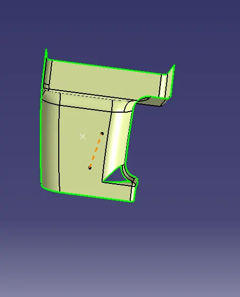
here i got ony one patch open and i used multi-section Surface tool to fill it up.
Class C Surface:-
To generate the class C surface, I utilized the sweep command within the geometric shape design workbench. Initially, I extracted the edges of the class A surface with tangent continuity, using the multiple extract command. Once I had successfully extracted the class A surface edges, I then proceeded to sweep these edges with a 90 degree angle towards the class B surface. Following the sweeping of the class A surface edges, I extrapolated the edges of the sweep by 5mm in order to intersect them with each other.To create a complete sweep surface towards the class B surface, I trimmed the extrapolated surfaces together. I then trimmed sweep surface and the class A surface to obtain a single surface for the class A&C surfaces.
In order to create a solid body for the door handle, a closed surface was required. To achieve this, I trimmed the class B surface using the joined class A+C surface, effectively creating a closed surface for the door handle.
Closed Solid Body:-
To create the solid body I used the closed surface command in the part workbench. Click on the closed surface command in the part workbench and give the closed surface as an input to create the solid part body.
Creating Rib :-
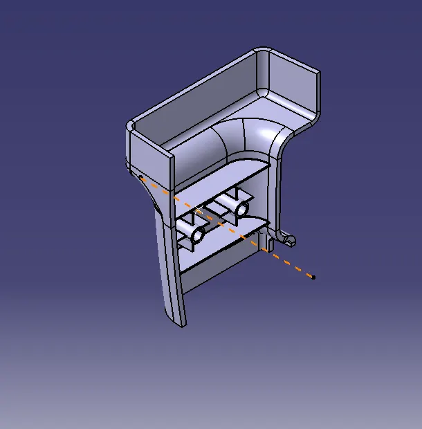
In order to create the ribs on the solid part body, I followed the design guidelines provided. Initially, I created a line sketch for the rib and extruded it in the direction of the tooling axis. I then thickened the extruded surface by 1mm towards the outside.
After thickening the extruded surface, I applied a 0.5 degree draft angle to the rib. To incorporate the rib into the main part body without any unwanted extra parts, I used the union trim function to remove any excess surface material from the rib.
Once the rib was successfully added to the part body, I applied a fillet to it with a radius of 0.25mm, in accordance with the maximum fillet radius specified in the design parameters. I repeated this process to create rib-2, using the same design guidelines.
Screw Boss Creating:-
To create the screw boss, I first created a circular sketch using the sketcher workbench. I then padded the sketch to a thickness of 13mm.
After padding the sketch, I applied a 0.5 degree draft angle to both the inside and outside surfaces of the screw boss in the tooling axis direction. Once this was completed, I applied a 0.25mm fillet to all sides of the screw boss.
Next, I translated the screw boss to the right side for a distance of 30mm. To ensure that the screw boss remained stiff and rigid, I added 4 supporting ribs for each screw boss.with 10mm height upwards and 1mm downward direction. so that both can assemble together with body without creating any problem.
Draft analysis for Part with Screw boss and ribs:-
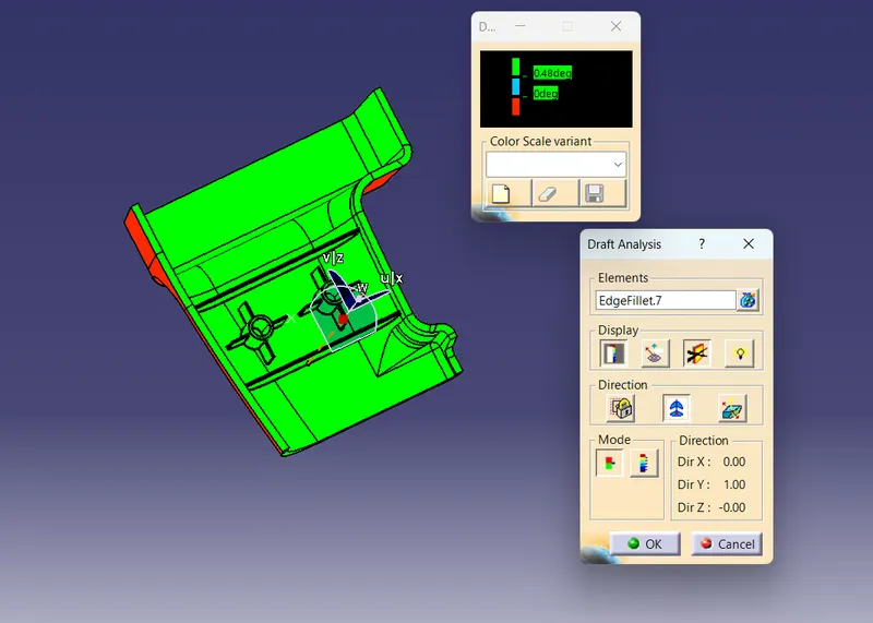
To perform the draft analysis for the solid part body that included ribs and screw bosses, I used the draft analysis tool in the generative shape design workbench. I began by aligning the compass to the tooling axis and selecting the solid part body.
I set the draft angle in the colour bar to 0.9 degrees. However, I observed that some faces did not clear properly when I set the draft angle to 3 degrees in the colour bar. This was likely due to the draft angle and curvatures present on the class A surface in the bottom area of the solid body. As a result, the solid body was shown in red and cyan colours even though the draft angle was set to 0.9 degrees.
Despite this, I could not decrease the draft angle to less than 0.5 degrees due to the design requirements of the plastic component, which called for a draft angle of 0.5 degrees to 3 degrees.
DIfferent Views:-
Isometric View-
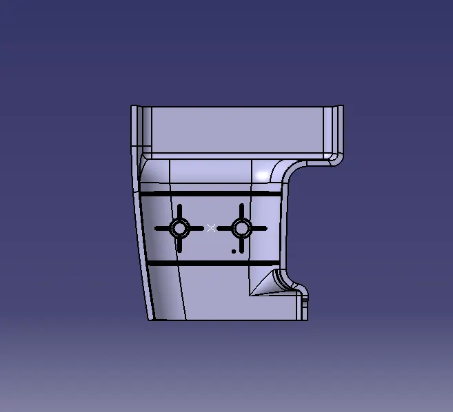
Front View:
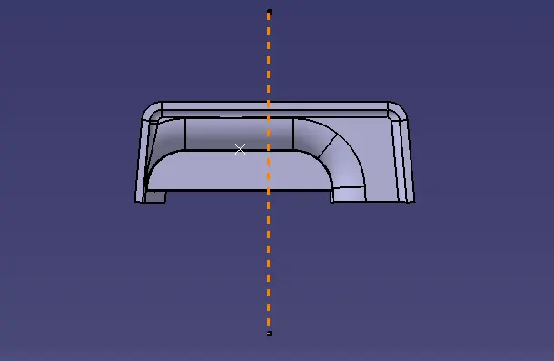
Top View:
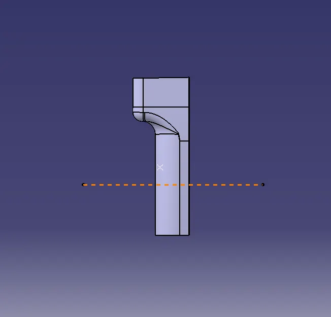
Side View:
Geometric set:-