Wiring harness design in CATIA V5 - 3D modeling Week 2 Challenge
CONNECTORS
AIM:
To download the following connectors & Connector clip cad data from given link & define it as Electrical Connector using Electrical Part design Workbench. Define all the necessary properties to Connectors & Clip.
- · Deutsch DT06 - 08SA - (https://www.te.com/usa-en/product-DT06-08SA.html)
- · Tyco174357-2 - (https://www.te.com/usa-en/product-2-174357-2.html?source=header-match)
- · Tyco85229-1- (https://www.te.com/usa-en/product-85229-1.html?q=85229&source=header)
INTRODUCTION:
A wiring harness connector is a device used to join multiple electrical wires within a wiring harness, ensuring a secure and organized connection. It facilitates the transmission of electrical signals or power between different components in a system, such as in automobiles, industrial machinery, and electronic devices.
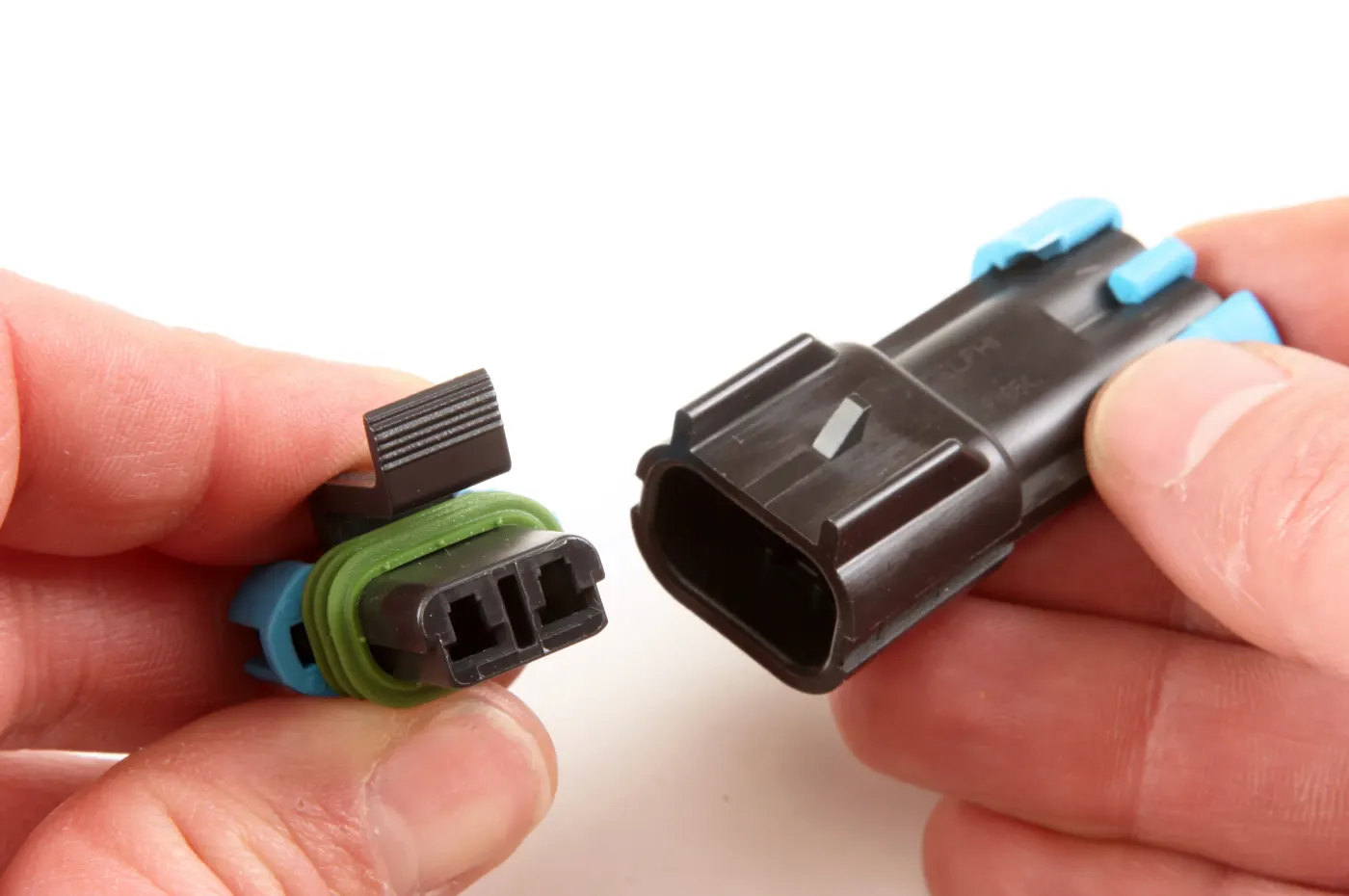
Key Functions of a Wiring Harness Connector:
- Electrical Connection – Ensures efficient transmission of power and signals.
- Mechanical Support – Keeps wires securely attached, reducing wear and tear.
- Protection – Shields wires from moisture, dust, and vibrations.
- Ease of Maintenance – Allows for quick assembly, disassembly, and replacement of wiring components.
CONNECTOR DEFINITION:
- · Following Parameters are required to defined for any connector -
- · Geometry Parameters - Points & Co-ordinate system (Axis)
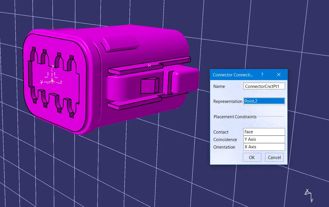
- · Connector connection points - This point is used for the connection of one connector to another connector.
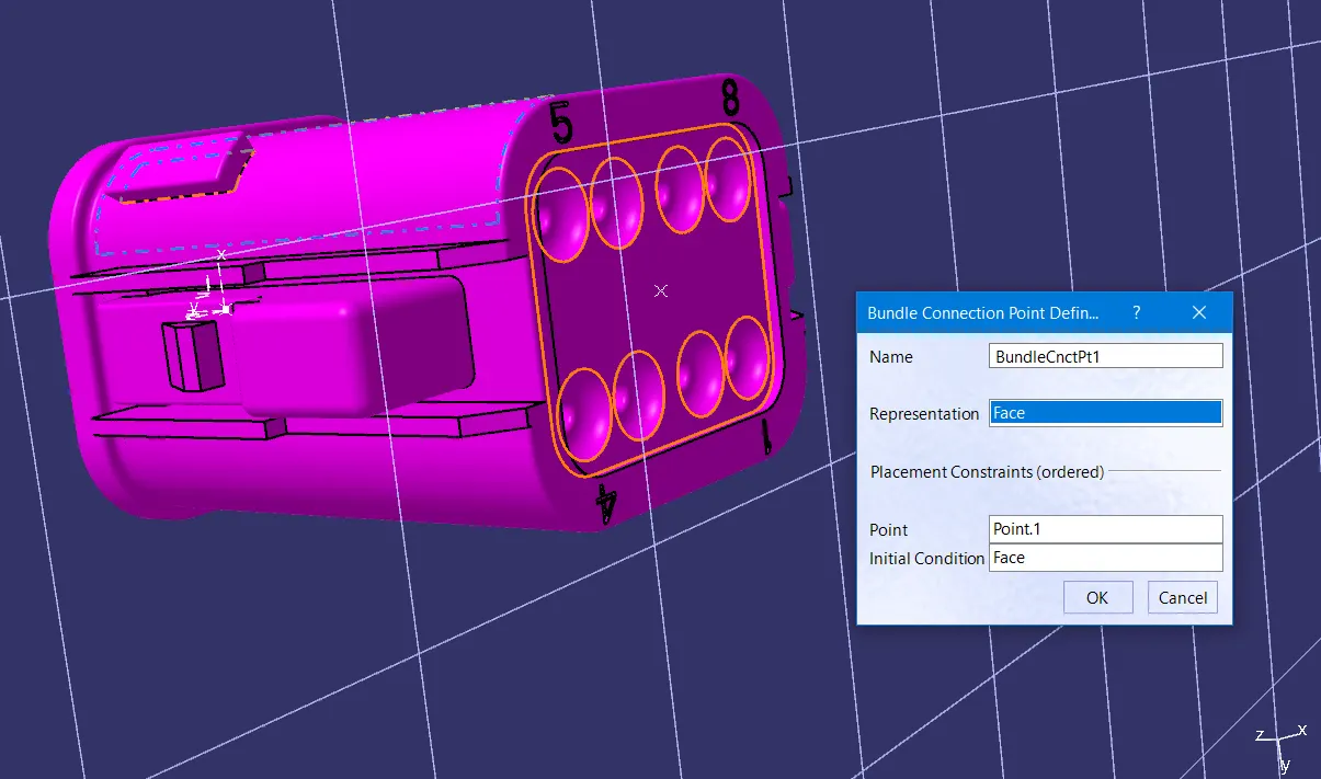
- · Harness bundle entry point - This point defines where the harness bundle segment point will end when routed to the electrical connector.
- · Cavity connection point (Optional) - This point is used to define the connection of a connector to a connector clip. This only applies to connectors which have the mounting feature for a connector clip.
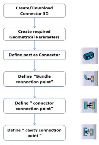
CONNECTOR DEFINATIONS IN CATIA V5:
1.Deutsch DT06 – 08SA
Creation of connector connection point:
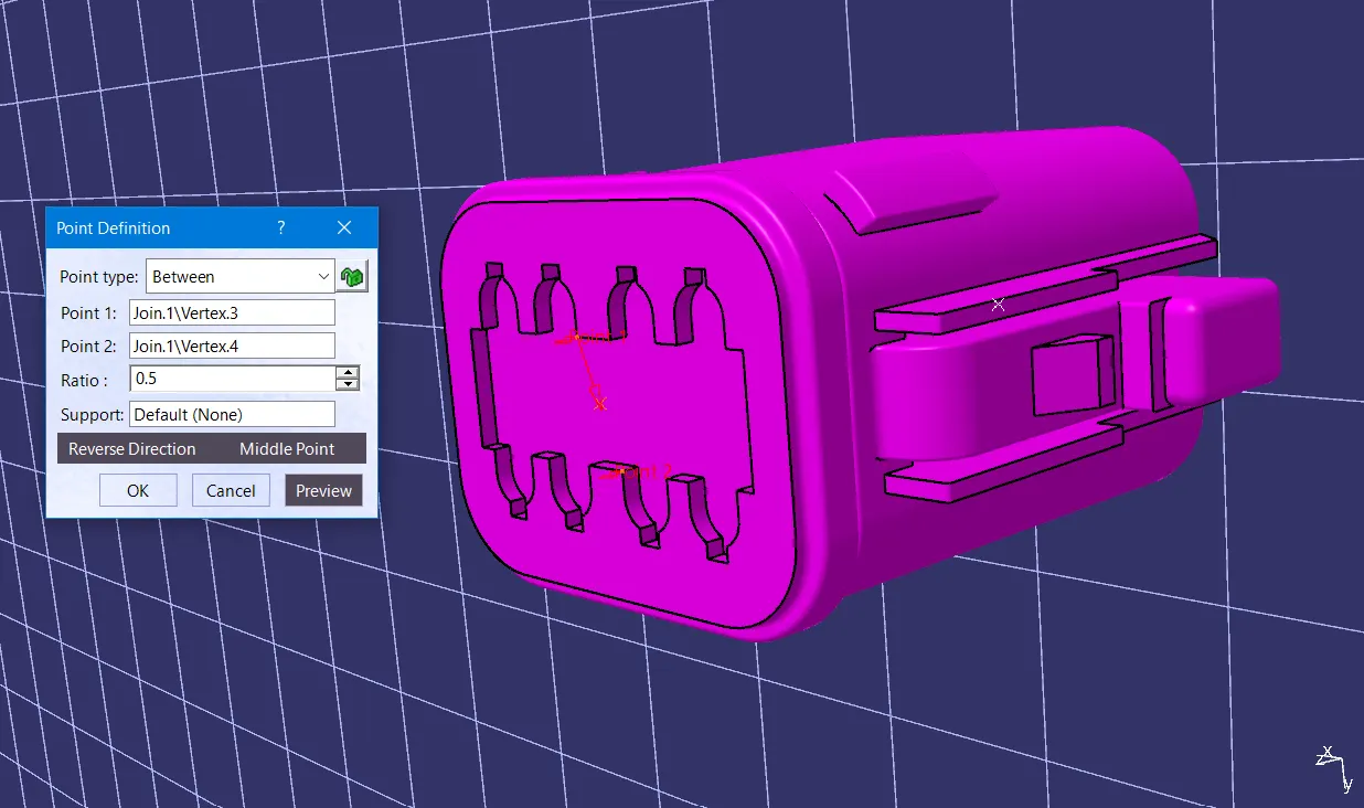
Creation of axis system with respect to the point which we have created and defining the axis direction:
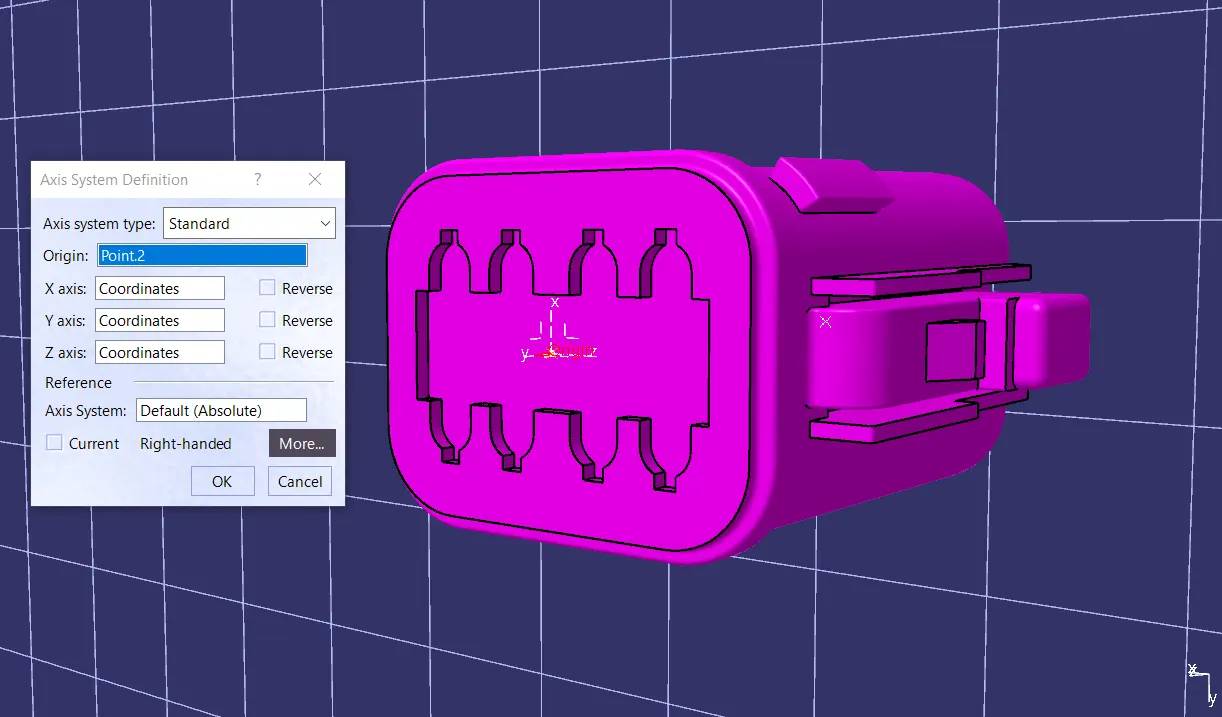
Creation of bundle entry point:
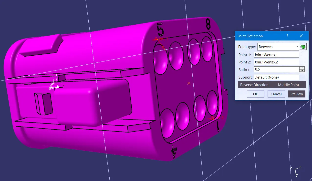
Switch to 'Electric Part Design'
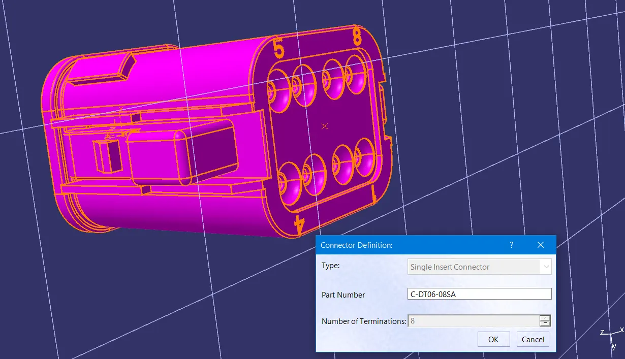
Define the part as connector in CATIA and give numbers of termination as 8 because we have 8 entry points for wire.
Define Bundle connection point:
Define connector connection point:
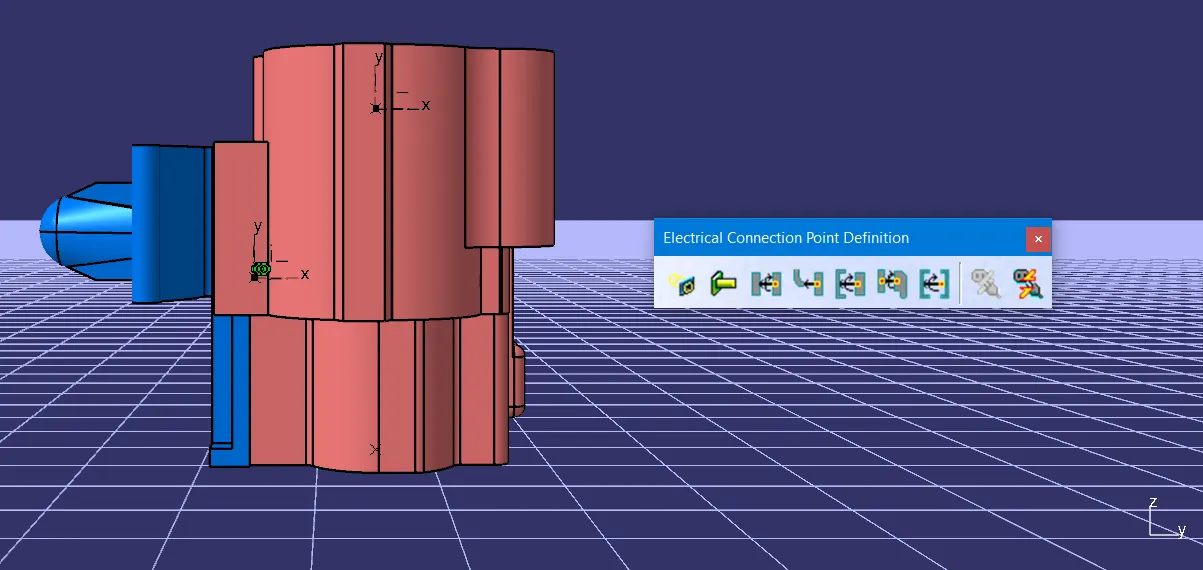
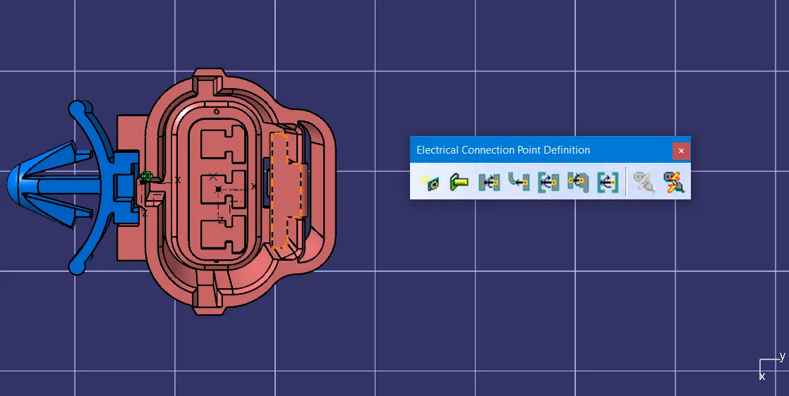
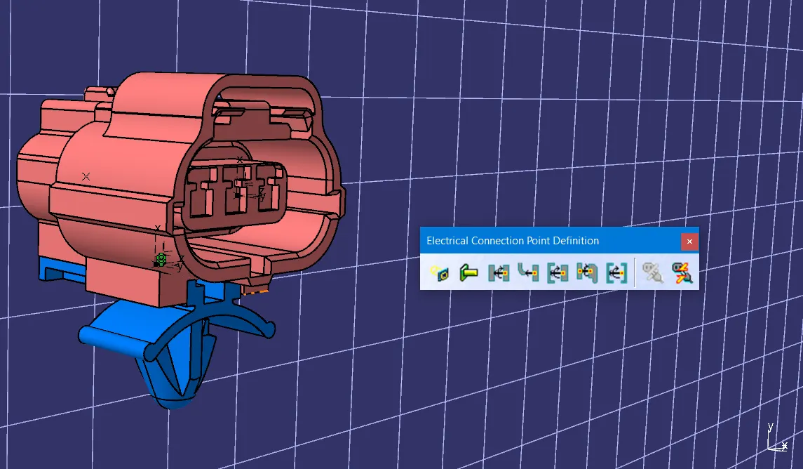
2. Tyco 174357-2:
· Creation of connector connection point
· Creation of connector connection axis system
· Creation of bundle connection point
· Creation of cavity connection point
· Creation of cavity connection axis system
· Switch to Electric part design and define part as connector
· Define Connector connection point, Bundle connection point and cavity connection point.
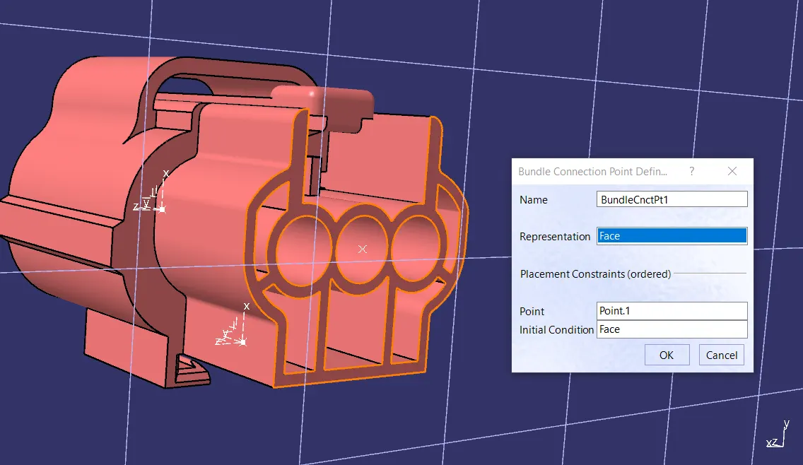
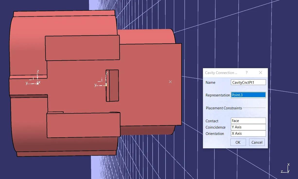
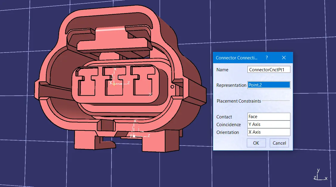
3. Tyco 85229-1:
· Creation of cavity connection point.
· create cavity connection axis system and orientation should be same as in connector.
· Switch to Electric part design and define part as Mounting Equipment.
· Define cavity connection point.
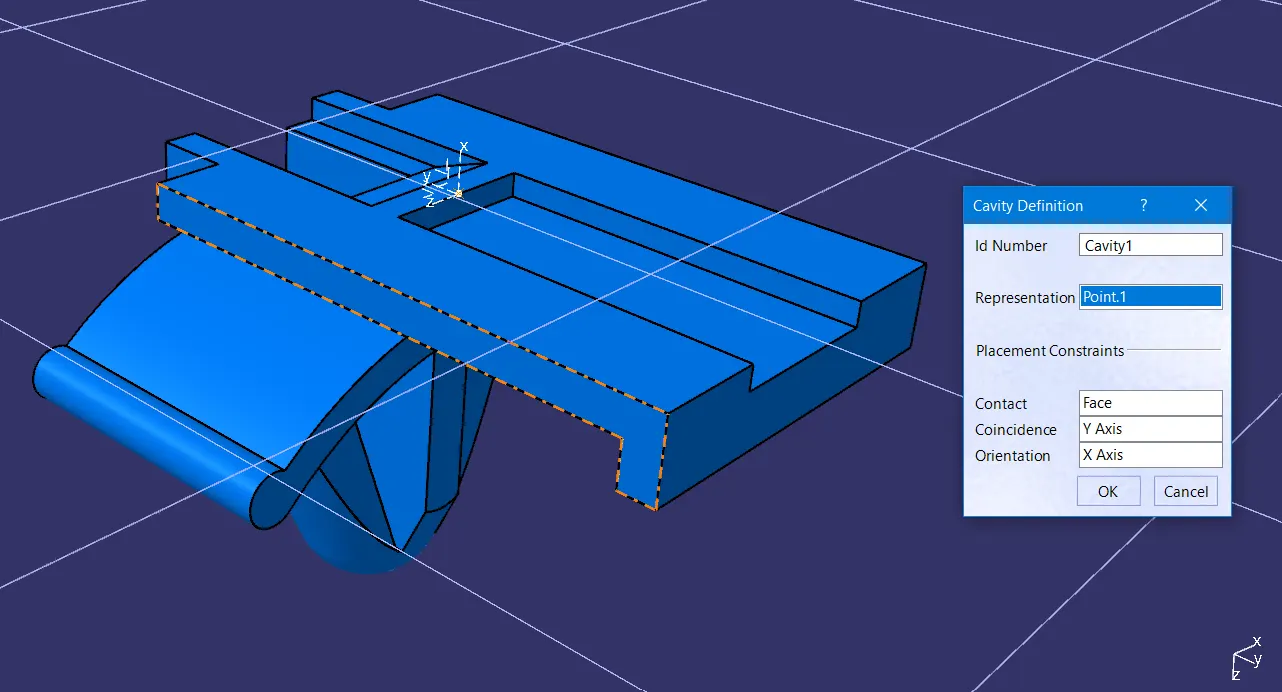
Electrical Assembly Design:
· Import Connector and cavity / mounting clip.
· Select Define Electric connection.
· Select cavity and then connector for done assembly.
Conclusion:
Hence all components are defines as required, and also added to the catalogue.