Wiring harness design in CATIA V5 - 3D modeling Week 2 Challenge
Title: Defining Connectors and Clips using CATIA V5.
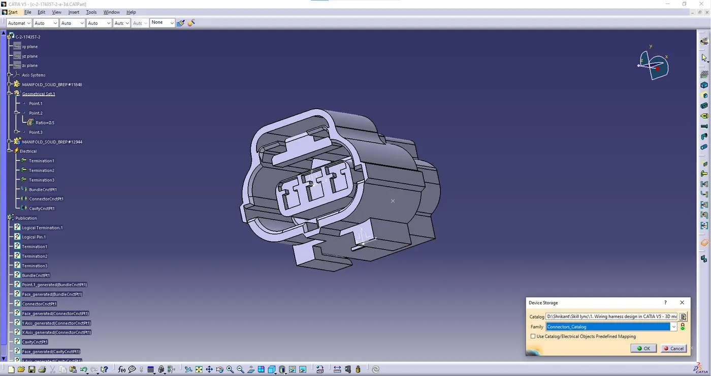
Objective: Downloading the 3D CAD files form the te.com website and then defining the parts electrically and further creating a catalogue for the components.
Procedure:
A) Defining Deutsch DT06-8SA & Tyco 174357-2 Connectors connections
1) Open the connector in part design
2) Define Harness bundle point at the entry point of wire bundles of connectors.
3) Define Connectivity axis system on the mating face where the male & female connectors contact.
4) The axis system must be defined such that the
- Y axis should point towards front face of the connector
- X axis should be pointing in the direction towards locking mechanism of the clip.
- Z axis should be pointing across the connectors from left to right.
5) Define proper clip axis system on the mating point of the mounting clip for connector.
6) Now open the part in electrical part design to define necessary electrical properties. It requires 4 properties to be defined for connectors.
7) To define part as Connector, use connector command & define the part, its type & no. of terminations.
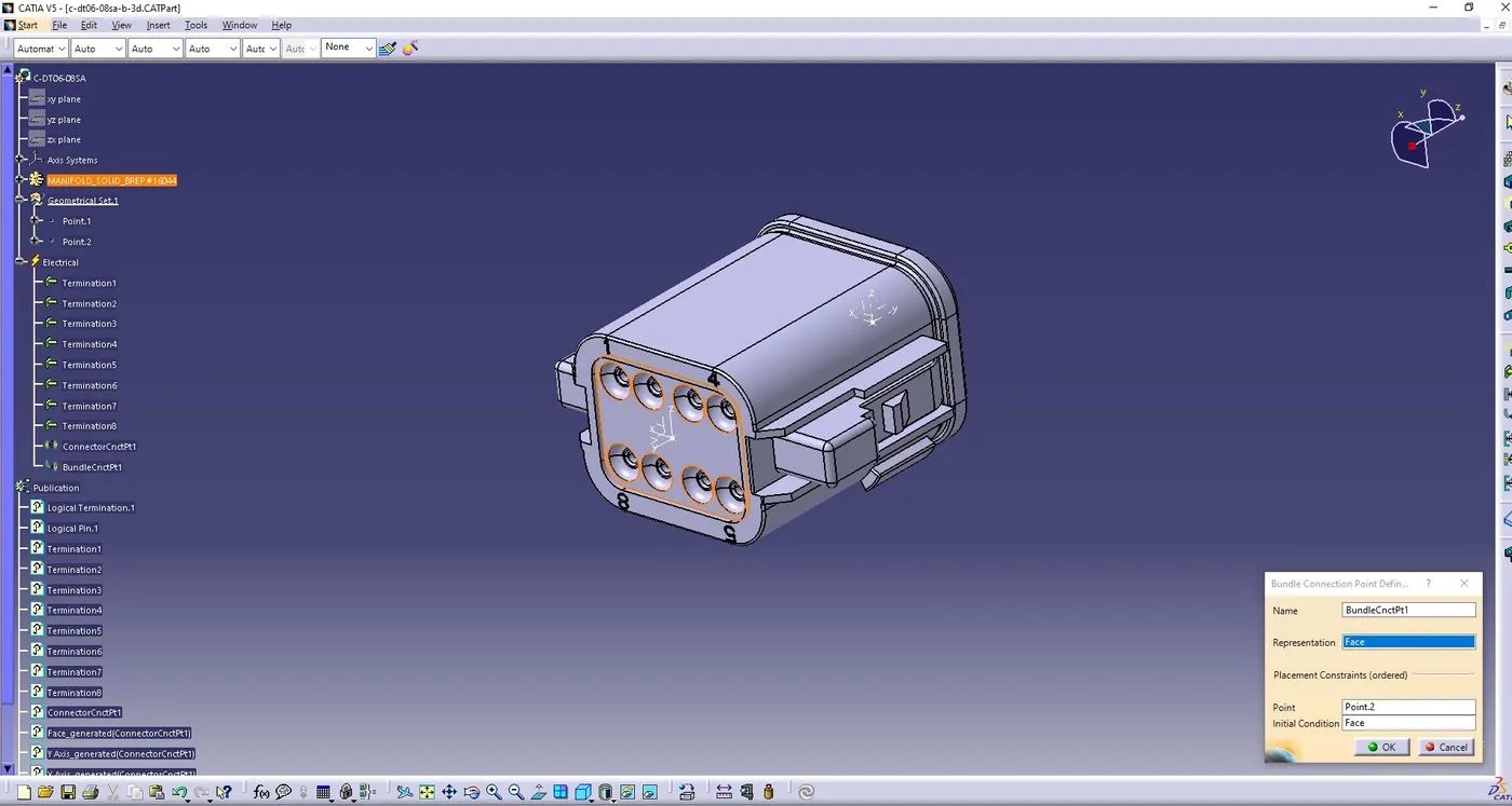
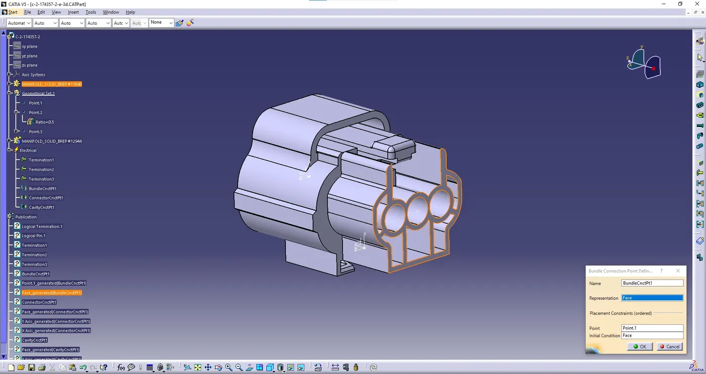
8) To define bundle connection point use bundle connection point command &define the part,
- Define the part
- Representation (which is the entry face of the connector)
- Point (which is the bundle entry point defined in part design)
- Initial condition (which is the same face as selected in representation).
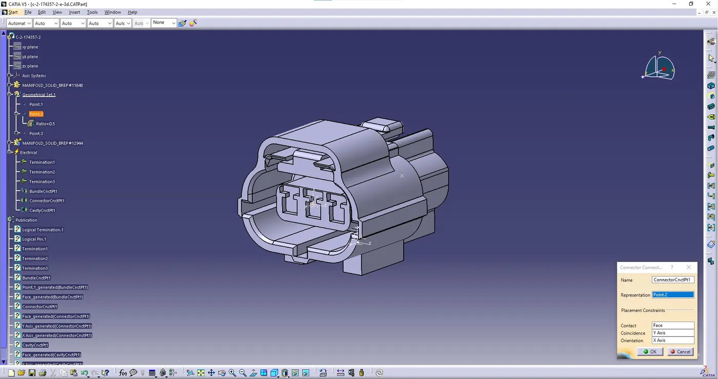
9) To define connector connection point use connector connection point command &
- Define the part
- Representation (which is the connector connection point)
- Contact (which is the mating face with another connector)
- Coincidence (which is the Y axis)
- Orientation (which is the X axis).
10) To define cavity connection point use cavity connection point command &
- Define the part
- Representation (which is the cavity connection point)
- Contact (which is the mating face with connector clip)
- Coincidence (which is the Y axis)
- Orientation (which is the X axis).
11) Hence both the connectors are defined as electrical parts as in the images below.
1. Deutsch DT06-8SA
BUNDLE CONNECTION POINT DEFINATION
CONNETOR CONNECTION POINT DEFINATION POINT 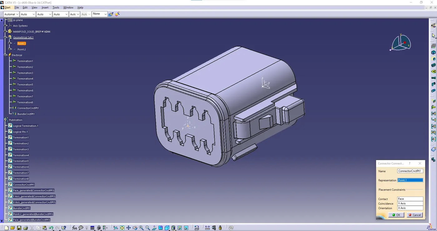
2. Tyco 174357-2
BUNDLE CONNECTION POINT DEFINATION
CONNECTOR CONNECTION POINT DEFINATION
CAVITY CONNECTION POINT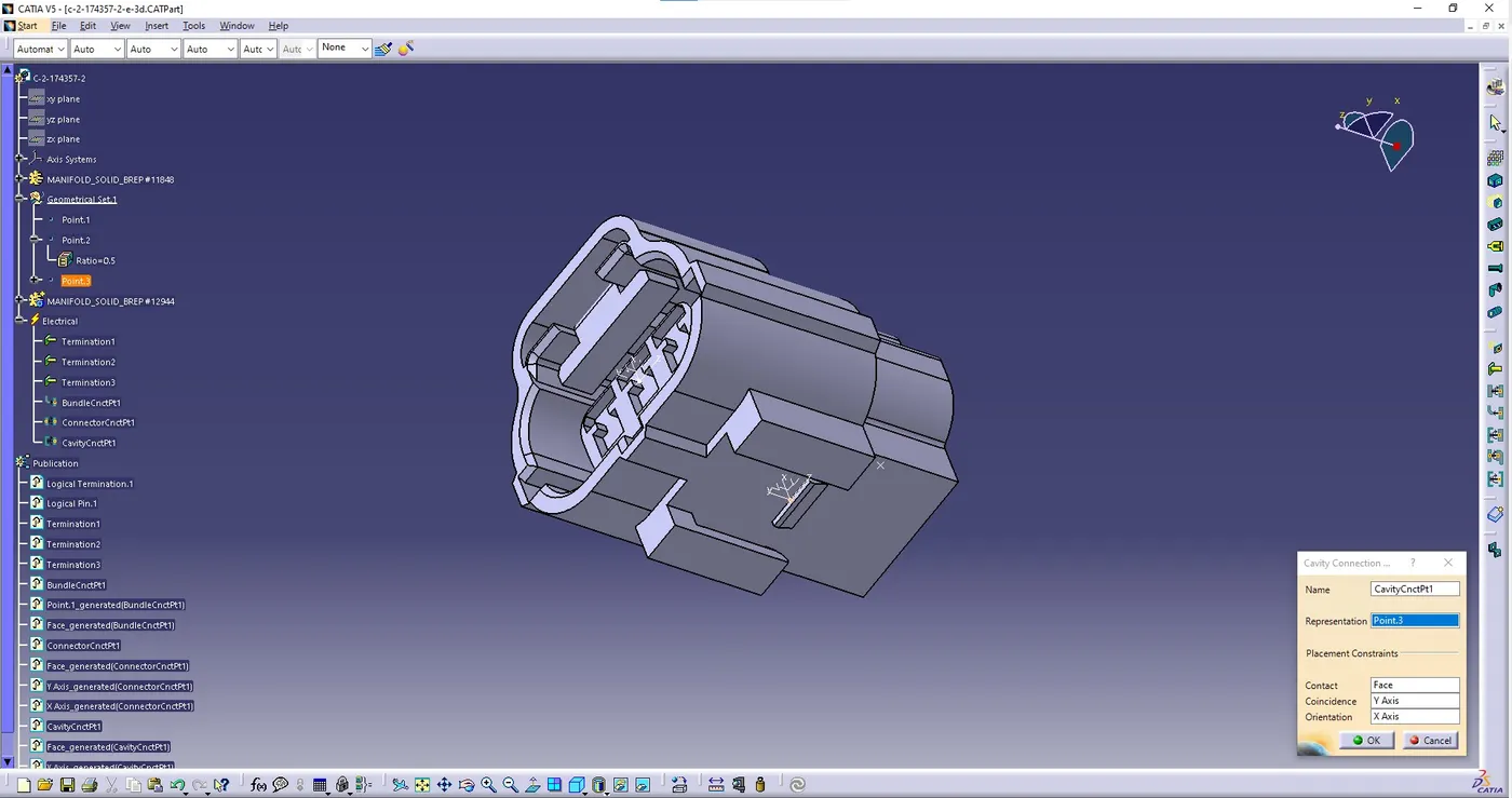
B) Defining Tyco 85229-1 Clip connections
1) Open the mounting clip in the part design
2) Define proper clip axis system at the mating point of the connector connection on the mounting clip. Ensure same axis system directions as provided in the mating part (connector).
3) Go to Electrical part design
4) To define clip as mounting equipment, use mounting equipment command & define the part.
5) To define clip as cavity, use cavity command &
- Define the part
- Representation (which is the cavity connection point upon the clip)
- Contact (which is the mating face with connector)
- Coincidence (which is the Y axis)
- Orientation (which is the X axis).
6) Hence the clips are defined as electrical parts as in the image below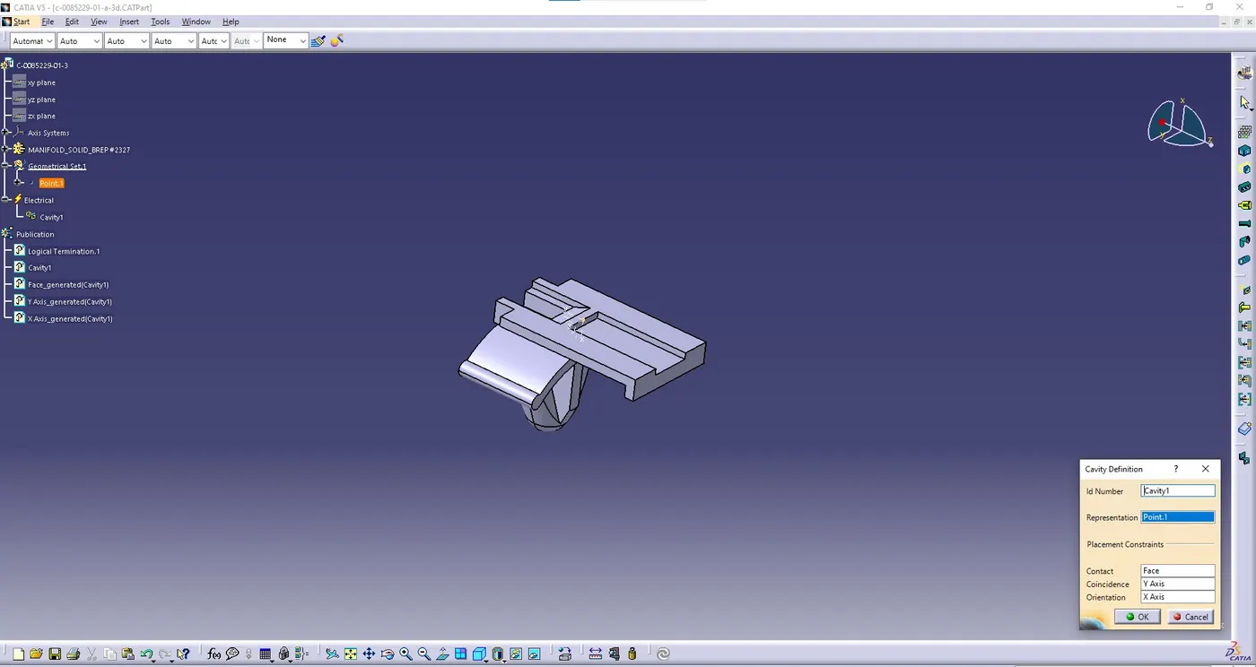
CAVITY DEFINATION
C) Assembly of Tyco174357-2 & Tyco 85229-1 Clip
1) Copy both Tyco 174357-2 & Tyco 85229-1 and paste them in "Electrical Assembly design".
2) Compare both the part and make sure the direction of X and Y should be same.
3) In electrical assembly workbench try to manipulate parts using compass after getting them in proper parallel face.
4)At last, try to align them with the help of "connect electrical devices" option final assembly will look like this.
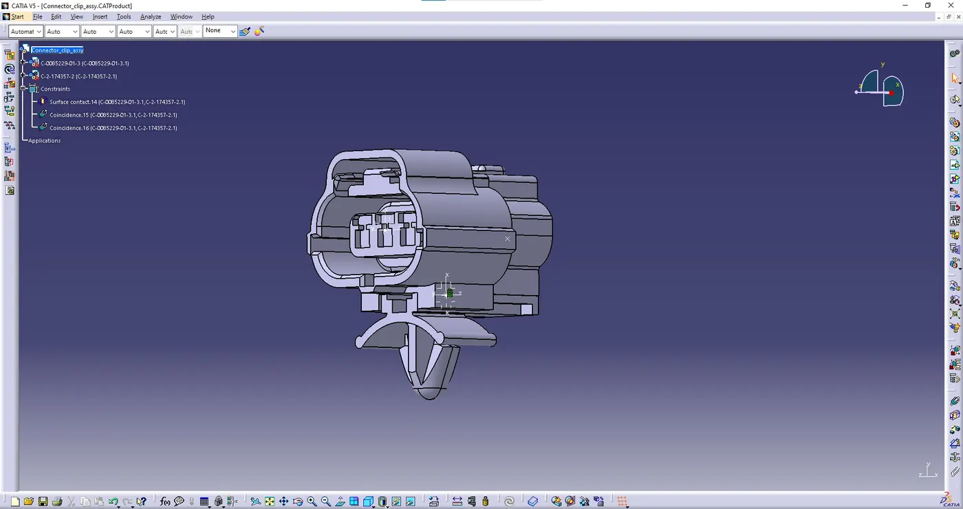
D) CatLog creation
1) Go to file - New - CatLog Document & click ok.
2)New CatLog Document will open then try adding family by using command "ADD FAMILY".
3) Family Definition window will pop-up, select Name & Type & click ok.
4) Then save it to desired folder as CatLog.
5) Open the data, define it electrically or give standard definitions it.
6) Select store devise option & select CatLog which is save earlier & select family & save it.