Wiring harness design in CATIA V5 - 3D modeling Week 2 Challenge
OBJECTIVE: Define the given connectors & connector clip cad data as Electrical Connector using
Electrical Part Design Workbench. Define all the necessary properties of Connectors & clip.
INTRODUCTION: A connector is a device ( or more precisely , a mating pair of devices , often
a plug and a socket ) for connecting together two or more wires , cable or hoses allowing electricity
or fluid to flow but also allowing easy disconnection and reconnection when necessary.
Mounting clips are used for supporting conduits. These clips are made of High-Quality impact
Resistant polyamide. The mounting clips are stackable and are fixed with the help of screws
onto the panel or equipment surface.
CONNECTION DEFINITION:-
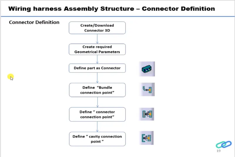
The following parameters are required to define any connector.
Geometry Parameters: Points & Co-ordinate system ( Axis ).
Connector connection point: This point is used for the connection of one connector to
another connector.
Harness bundle entery point: This point defines where the harness bundle segment point
will end when routed to the electrical connector.
Cavity connection point ( Optional ): This point is used to define the connection of a connector
to a connector clip.
- Deutsch DT06 – 08SA ( https://www.te.com/usa-en/product-DT06-08SA.html)
- Tyco 174357-2 (https://www.te.com/usa-en/product-2-174357-2.html?source=header-match)
- Tyco 85229-1 – (https://www.te.com/usa-en/product-85229-1.html?q=85229&source=header)
Connector 1: Deutsch DT06-08SA
1. Important the downloaded step or igs file in to the CATIA mechanical part workbench
2. Define the Bundle Entry Point.
3. Define the Connector Connection Point.
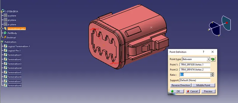
4. Define Connection Axis. Y- Axis should face the other mating part /direction and x- Axis should
face the lock
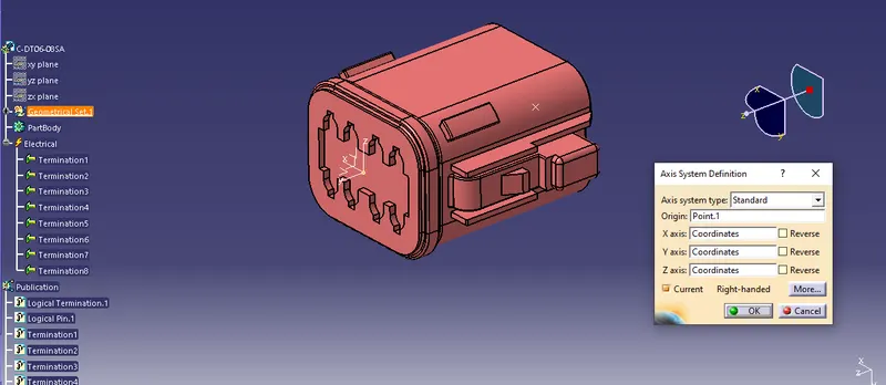
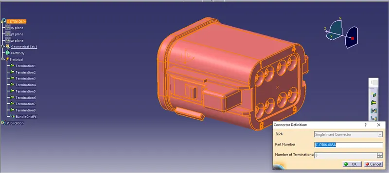
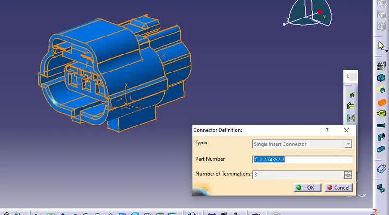
5. Now switch to the Electrical Part Design Workbenchand define the connector using
Define Connector Command with Name and No. Terminals.
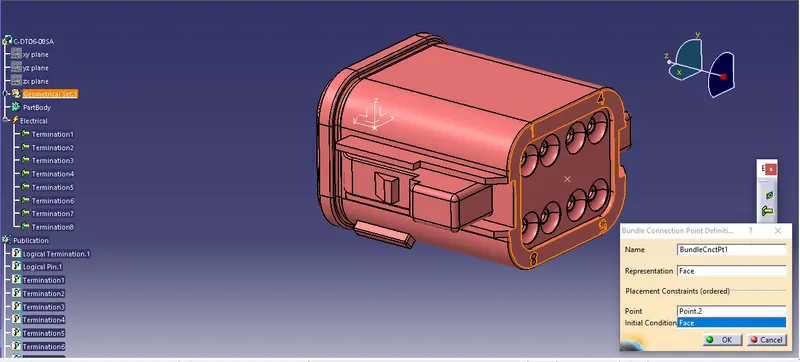
6. Define the Bundle Connection Point . Face as Representation , Bundle Entry Point as Point ,
and Same face as Representation for Initial Condition.
7. Define the Connector Connection Point . Connector Connection Point as Representation ,
Mating Face as Contact , Y- axis as Coincidence , and X-Axis as Orientation .
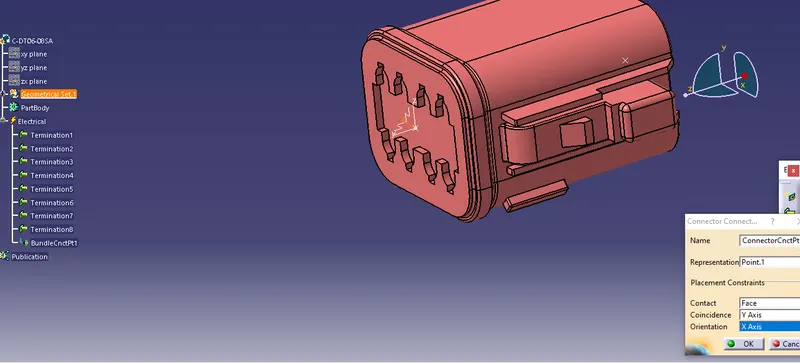
Connectors 2: Tyco 174357-2
1. Follow the same steps from 1 to 4 as we did not connector.
2. Define Bundle Entry Point , Connector Connection Point , and Connector Connection Axis ( Y- Axis
facing mating part / direction & X- Axis fcing lock ).
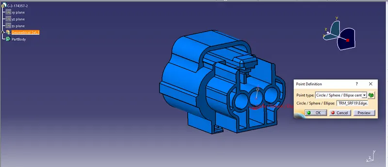
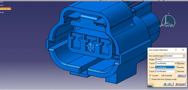
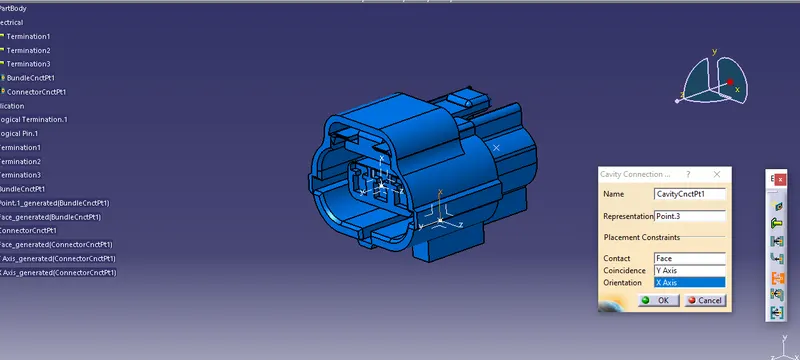
2. This connector has Clip / Mounting Cavity . So , define the Clip / Mounting Cavity point and
Clip / Mounting Cavity Axis ( Y- Axis facing mating part / direction & X - Axis facing lock)
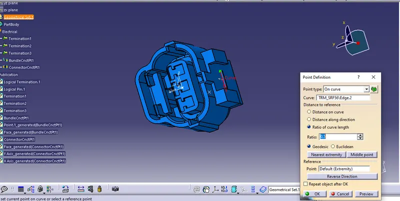
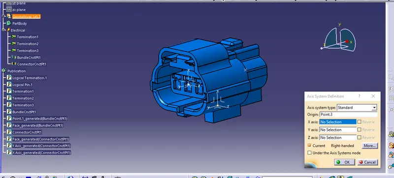
3. Now we followthe same steps from 5 to 7 as we did in Connector 1. Define as a connector
Bundle Connection Point , and Connection Point.
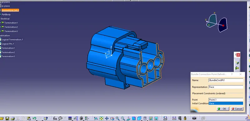
3. Define the Connector Clip / Mounting Cavity . Connector Clip / Mounting Points as
Representation , Mating Face as contact , Y - axis as Coincidence , and X - Axis as
Orientation .
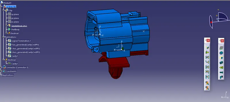
CONNECTOR CLIP Tyco 85229-1:
1. Import the downloaded step or igs file into the CATIA mechanical part workbench.
2. Define the Clip / Mounting Cavity Point and Clip / Mounting Cavity Axis ( Y- Axis facing
mating part / direction & X - Axis facing lock ) . The Cavity Axis should be similar to the
Connector Cavity Axis for the correct assembly of the parts.
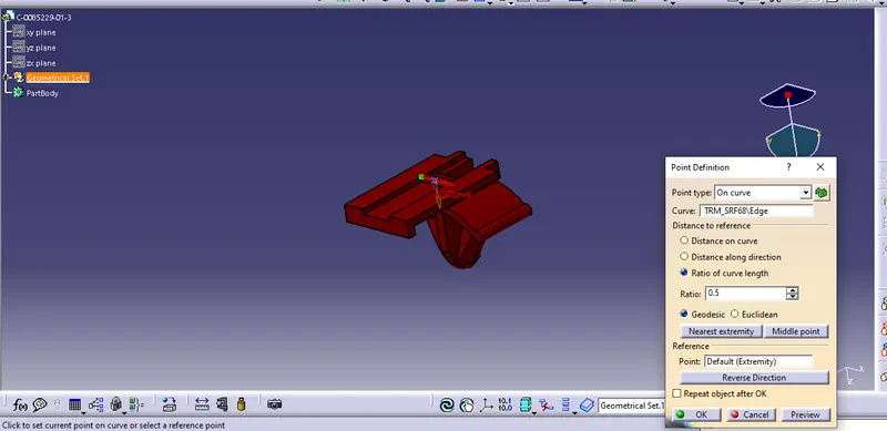
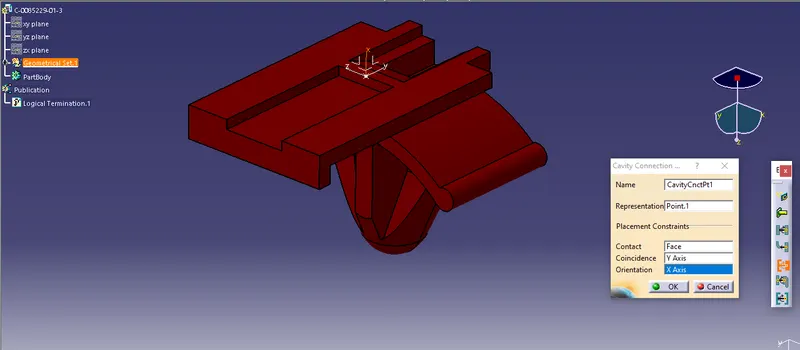
3. Define the Mounting Clip as Cavity . Connector Cavity Point as Representation , Mating
Face as Contact , Y - axis as Coincidence , and X - Axis as Orientation.
CONNECTOR AND MOUNTING CLIP ASSEMBLY
1. Import both the parts in the Electrical Assembly Design workbench andalign them
properly.
2. Using the Connect Electrical Devices command First select the Mounting Clip and then
Cavity Connection Point will show on the Connector in green color automatically.
3. Select the Highlighted green point and the parts will assemble togeher automtically in
the correct position with respect to the defined Connector Cavity Axis on both parts.