Wiring harness design in CATIA V5 - 3D modeling Week 2 Challenge
Objective: To define the Connector and Connector Clip CAD files as electrical parts with all the necessary properties using CATIA V5.
Data:
- Deutsch DT06 – 08SA ( https://www.te.com/usa-en/product-DT06-08SA.html)
- Tyco 174357-2 (https://www.te.com/usa-en/product-2-174357-2.html?source=header-match)
- Tyco 85229-1 – (https://www.te.com/usa-en/product-85229-1.html?q=85229&source=header)
Introduction:
Electrical Distribution System (EDS) is like the nervous system of the car which transfers power and data throughout the vehicle. It deals with physical and logical architecture, schematic development, power distribution, wiring harness design as well as wiring harness component design. Wiring harness is the system that enables this transfer. Let us start with the EDS design process. We have two aspects of the EDS design, the mechanical aspect, and the electrical aspect. Both processes occur simultaneously. Shown below is the typical design flow of EDS system.

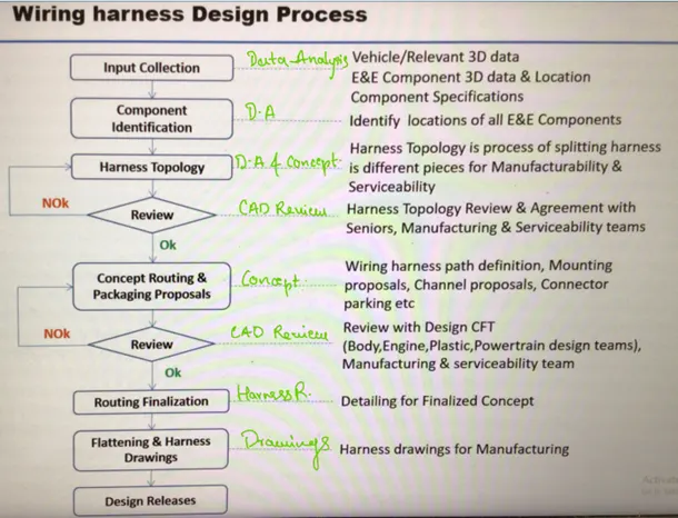
The wiring harness design process is shown below in the flow chart. The text written in green is the methodology used for each of the respective stages.
Connector:
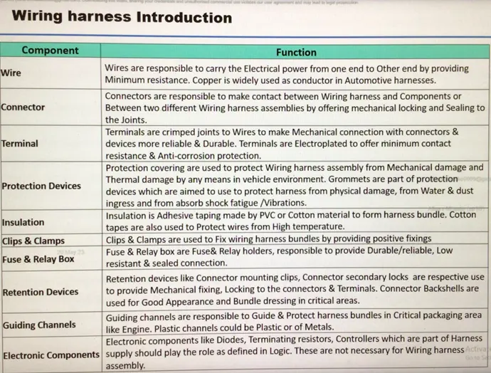
Connectors are responsible to make contact between the wiring harness and components. They can also make contact between two separate wiring harness assemblies by providing mechanical locking and sealings at the joints.
Other components of the wiring harness assembly are given in the table below.
Connector Definition in Catia V5:
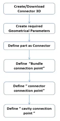
Design Flow in CAD Environment
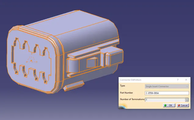
Deutsch DT06 – 08SA
1. Part Design:
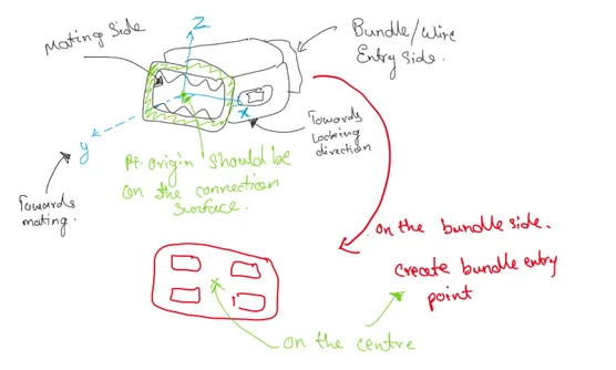
- Create two points one at the center of the mating side and the other at the center of the Bundle entry side.
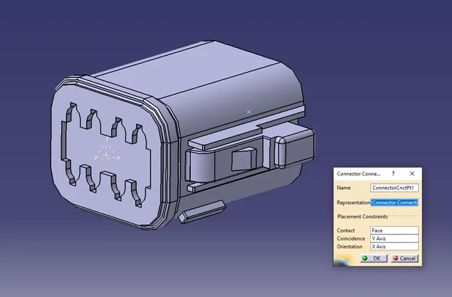
- Create an axis system as shown in the image below at the mating side.
2. Electrical Part Design:
- Define the part as the connector.
- Define Connector Connection Point.
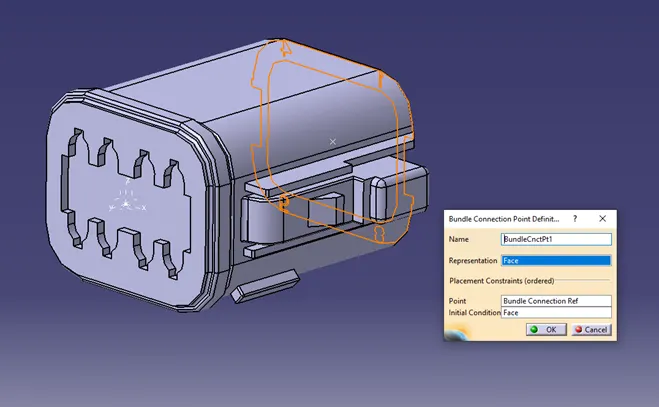
- Define Bundle Connection Point.
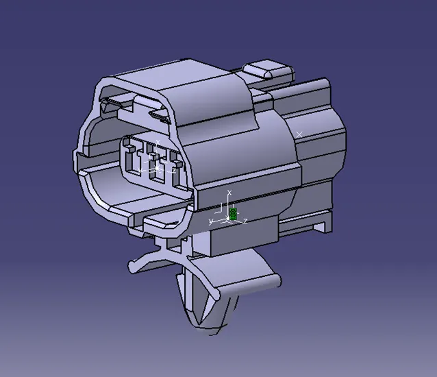
Tyco 174357-2
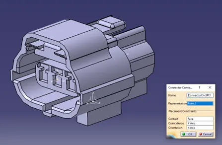
1. Part Design:
- Create two points one at the center of the mating side and the other at the center of the Bundle entry side.
- Create an axis system as shown in the image below at the mating side.
- Create another point and axis system at the cavity connection location.
2. Electrical Part Design:
- Define the part as the connector.
- Define Connector Connection Point.
- Define Bundle Connection Point.
- Define Cavity Connection Point.
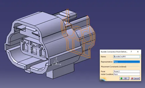
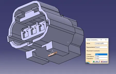
Tyco 85229-1
1. Part Design:
- Create a point and axis system in the same direction as the connector considering the assembly orientation.
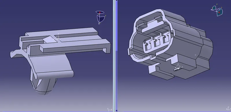
2. Electrical Part Design:
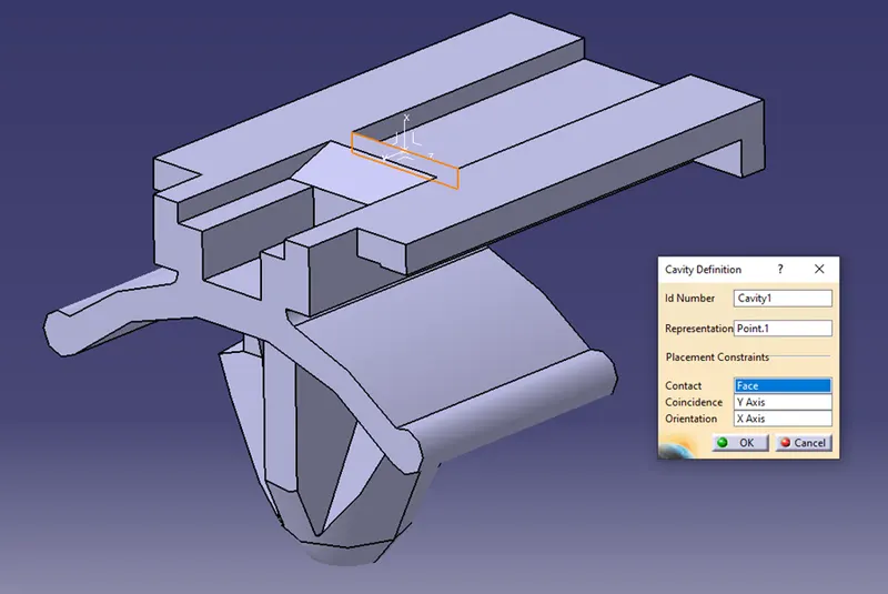
- Define the part as the mounting equipment.
- Define the whole part as the cavity.
Assembly of the Tyco 85229-1 and Tyco 174357-2
- Assembly Design:
- Align the parts such that they would assemble.
- Electrical Assembly Design:
- Connect the connector and cavity using the ‘Connect Electrical Devices’ command.
Conclusion:
Hence, we have successfully understood how to define a CAD part file as the electrical part in the virtual environment.