Wiring harness design in CATIA V5 - 3D modeling Week 2 Challenge
Objective:
Download 3D cad data from TE connectivity website te.com and then defining the parts electrically and creating the catalogue for connectors.
Descriptions:
Connector:
A connector is a device(or more precisely, a mating pair of devices, often a plug and a socket) for connecting together two or more wires, cables, or hoses, allowing electricity or fluid to flow but also allowing easy disconnection and re-connection when necessary.
Properties of Electrical Connectors:
Conductivity: Electrical connectors should have good conductivity to ensure minimal loss of electrical power across the connection.
Durability: Connectors should be designed to withstand repeated use, exposure to harsh environments, and mechanical stress without degrading their electrical performance.
Contact resistance: Connectors should have low contact resistance to ensure minimal voltage drop across the connection.
Insulation: Connectors should be designed to prevent accidental contact with live electrical parts, ensuring safety for the user.
Ease of use: Connectors should be designed to be easy to install and remove, and to provide secure and reliable connections without requiring specialized tools or skills.
Mounting Clips:
Mounting Clips are used for supporting conduits. These clips are made of High Quality Impact Resistant Polyamide. The mounting clips are stackable and are fixed with the help of screws on to the panel or equipment surface.
Properties of Mounting Clips:
Spring tension: Electrical clips should have the appropriate spring tension to ensure a secure and reliable connection between the clip and the component being connected.
Contact area: Clips should have a sufficient contact area to ensure good conductivity and minimize contact resistance.
Material: Clips should be made of materials that are resistant to corrosion, oxidation, and wear to ensure long-term reliability.
Size and shape: Clips should be designed to fit the specific components they are intended to connect, and should be appropriately sized and shaped to ensure a secure and reliable connection.
Insulation: Clips should be designed to prevent accidental contact with live electrical parts, ensuring safety for the user.
Design Methodology:
DEUTSCH DT06 - 08SA
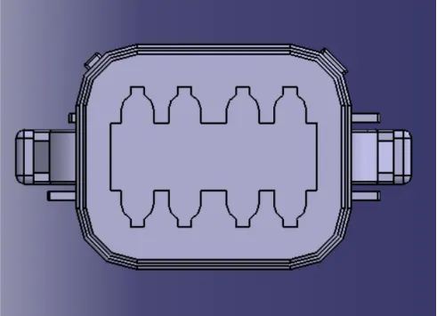
Connector Side View:
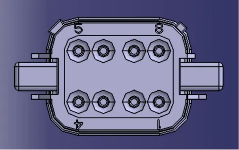
Bundle Side View:
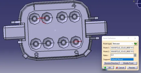
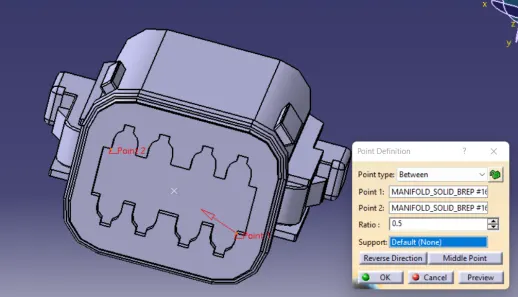
Creating Mid Point on Connector Side:
Creating Mid Point on Bundle Side:
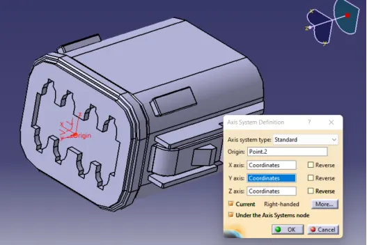
Creating Axis System:
The axis should be given in below mentioned specified way:
X-axis: Towards the clamp
Y-axis: Towards the connection
Z-axis: left or right of the connector
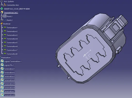
Define Connector:
Defining Connector Connection Point:
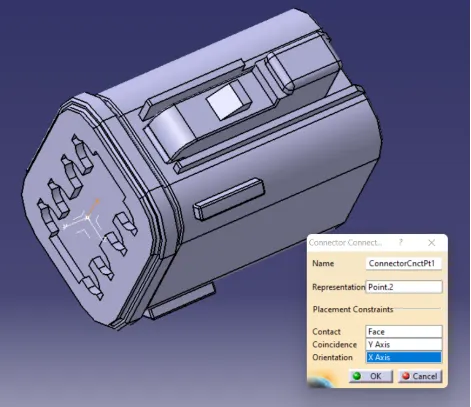
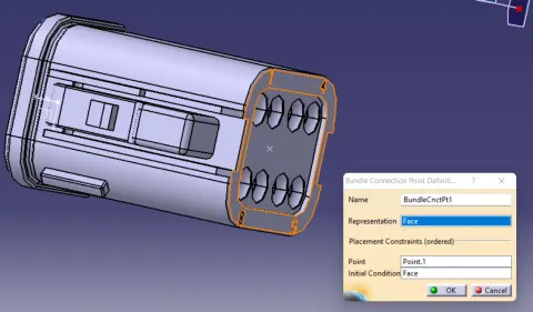
Define Bundle Connection Point:
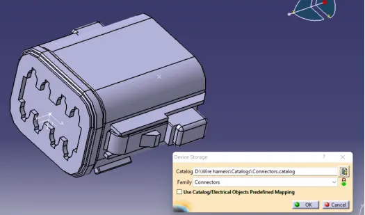
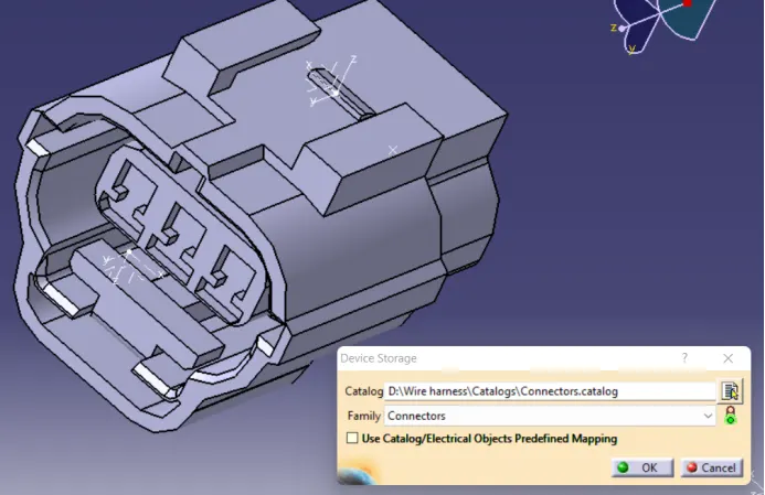
Device Storage:
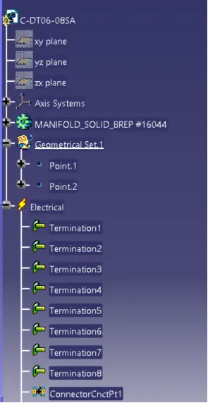
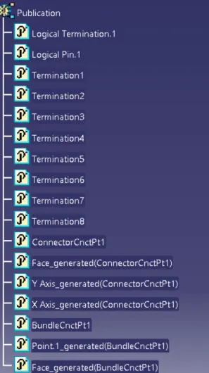
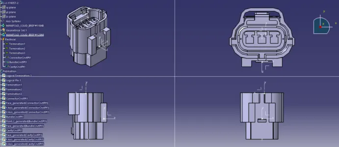
Feature Tree:
All Views:
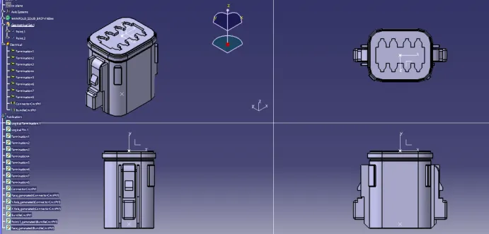
C-174357 - 2:
Connector Side:
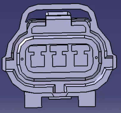
Bundle Side:
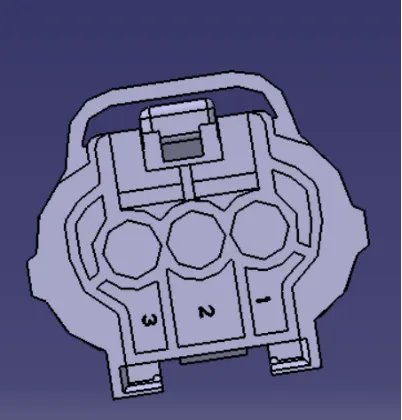
Creating Mid Point on Connector Side:
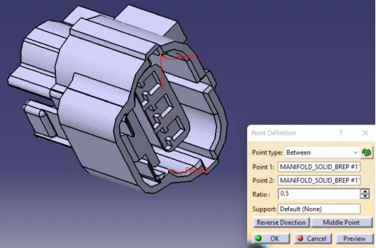
Creating Mid Point on Bundle Side:
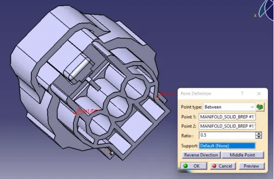
Creating Axis System:
The axis should be given in below mentioned specified way:
X-axis: Towards the clamp
Y-axis: Towards the connection
Z-axis: left or right of the connector
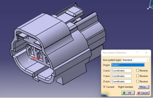
Define Connector:
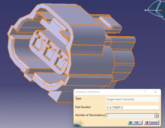
Connector Contact Point:

Connector Bundle Point:
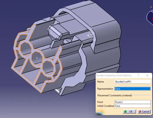
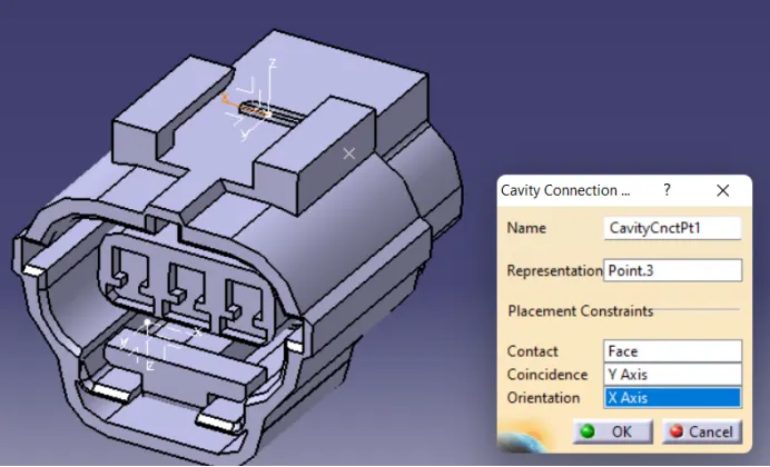
Creating Cavity Connection Point:
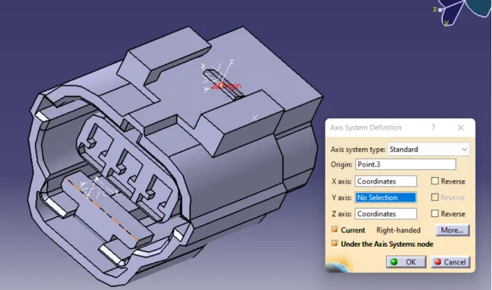
Cavity Connection Point:
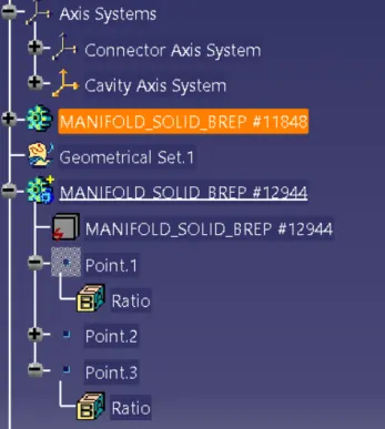
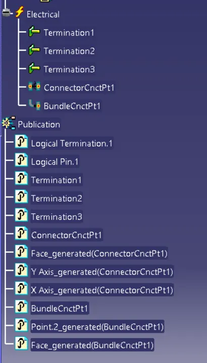
Feature Tree:
Final View:
Saving the Connector in Catalog:
TYCO 85229 - 1:
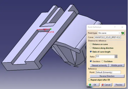
Creation of Point:
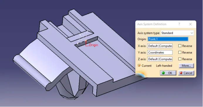
Creating Axis System:
The axis should be given in below mentioned specified way:
X-axis: Towards the clamp
Y-axis: Towards the connection
Z-axis: left or right of the connector
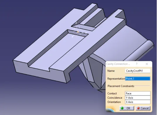
Define Mounting Equipment & Cavity Creating Point:
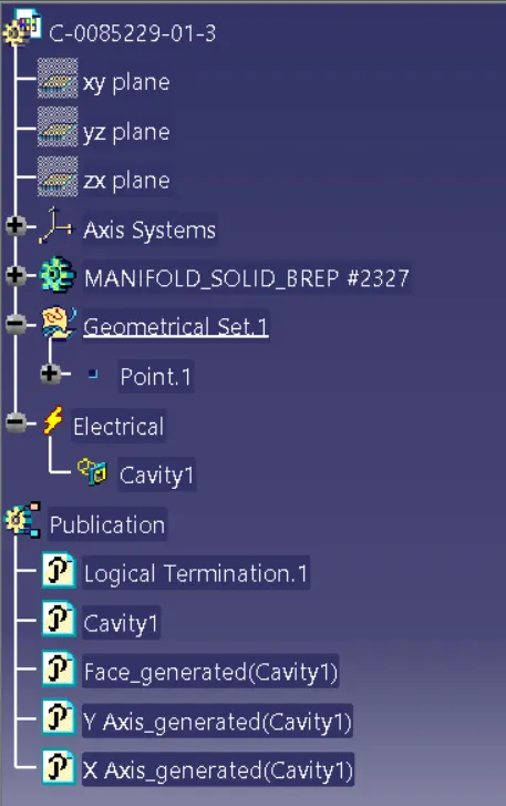
Feature Tree:
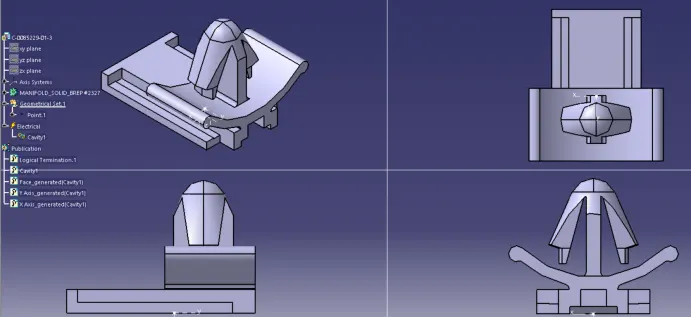
All Views:
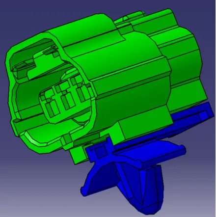
Assembly:
Import the Cad model of TYCO 85229 - 1 and C-174357 - 2 in Electrical Assembly Design workbench.
Select the Connect Electric Device command and select both the parts to get assembled.
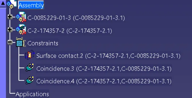
Feature Tree: