Wiring harness design in CATIA V5 - 3D modeling Week 2 Challenge
Wiring harness design in CATIA V5 - 3D modeling Week 2 Challenge
Electrical Definition and Catalogue Creation
The connector
We need to define the connector by following the below steps.
- Download the connector data.
- Create the required geometrical parameter.
- Define the part as an electrical connector.
- Define bundle connection point.
- Define connector connection point.
- Define cavity connection point.
The mounting clip
- Download the clip 3d data.
- Create the geometry parameter.
- Define the part as a mounting component.
- Define the part as a cavity.
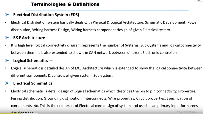
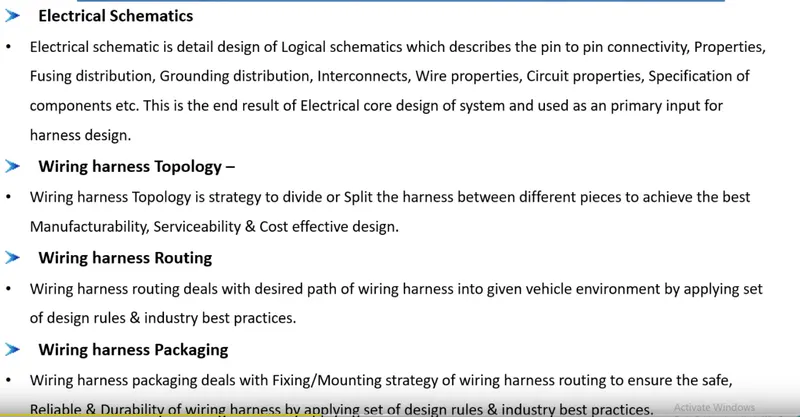
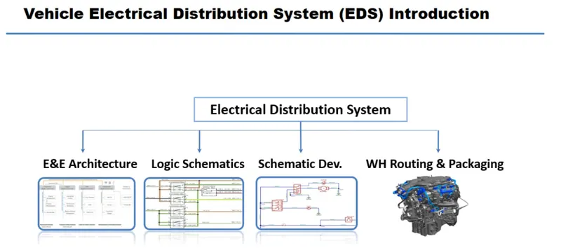
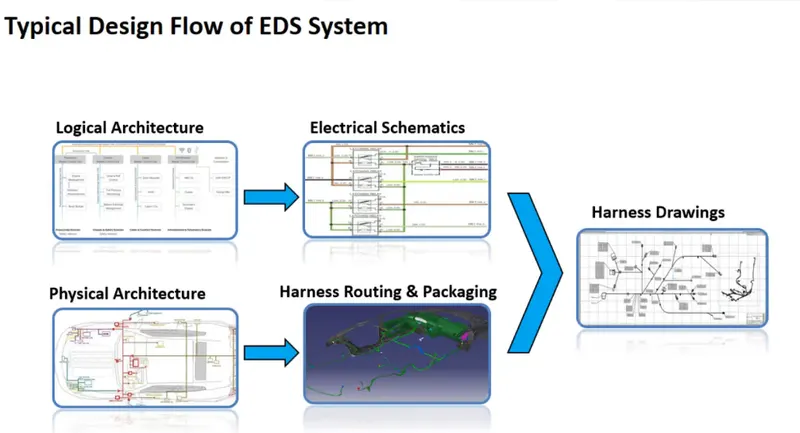
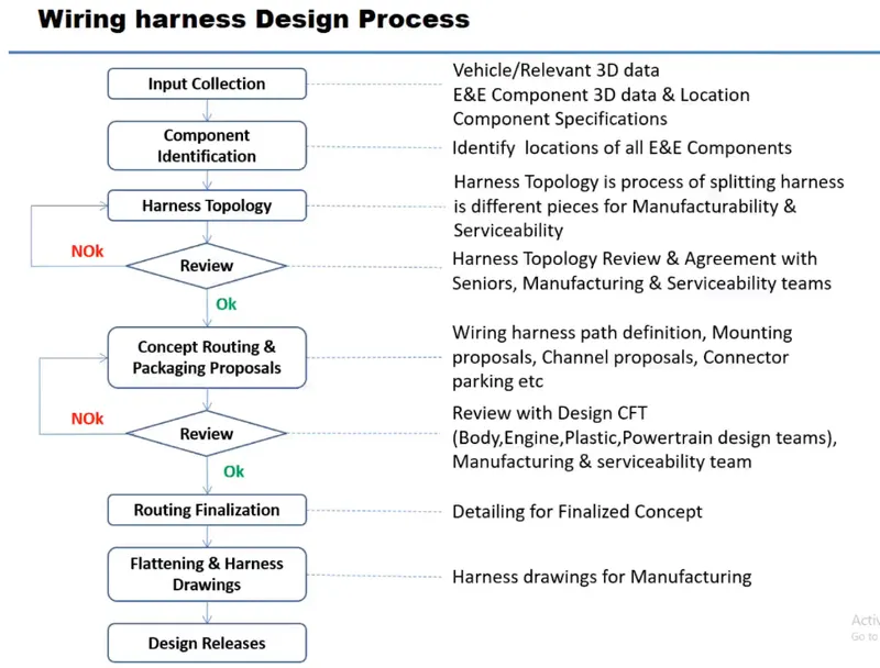
DEFINIG ELECTRIC PARAMETER FLOW CHART
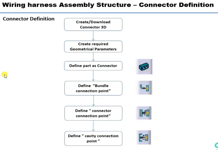
DOWNLOADED LINKS
I have Downloaded the 3D Model .igs files from the te.com website, as an Electrical wiring harness routing engineer to know the major and commonly used brands in the market as electrical components used for automobile
- Deutsch DT06 – 08SA ( https://www.te.com/usa-en/product-DT06-08SA.html)
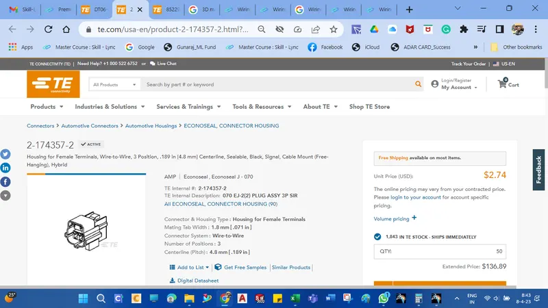
- Tyco 174357-2 (https://www.te.com/usa-en/product-2-174357-2.html?source=header-match)
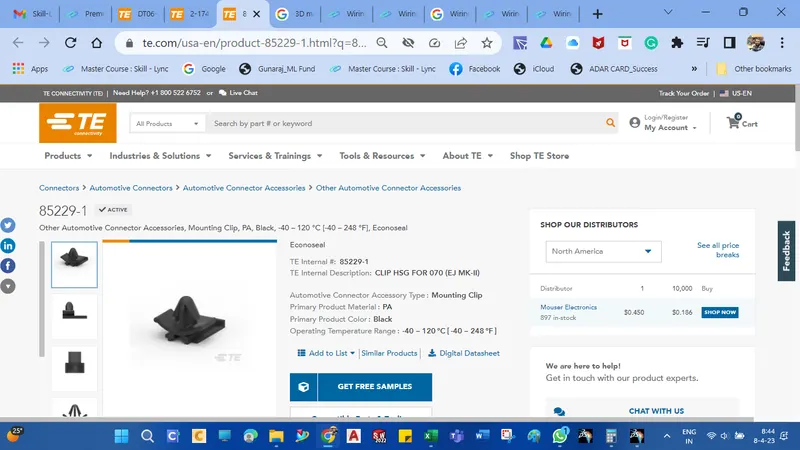
- Tyco 85229-1 – (https://www.te.com/usa-en/product-85229-1.html?q=85229&source=header)
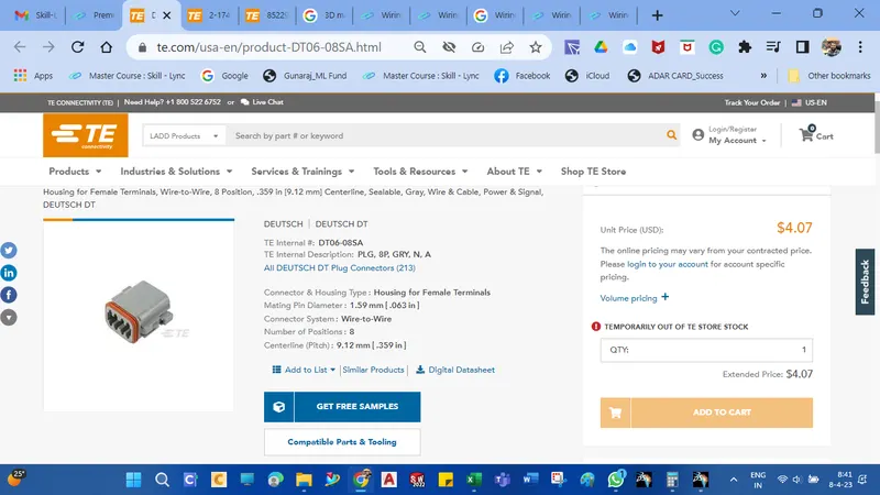
Downloaded the cad data from the supplier's website and the images are shown below.
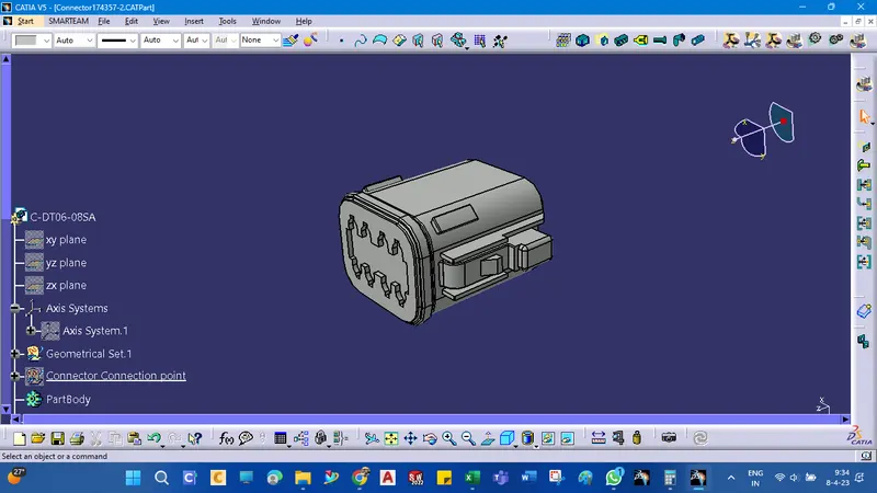
Deutsch DT06 – 08SA
Tyco 174357-2
Tyco 85229-1
CONNECTOR DEFINITION :
The following parameters are required to define any connector :
Geometry Parameters: Points & Coordinate system ( Axis ).
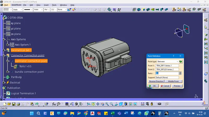
Connector connection points: This point is used for the connection of one connector to another connector.
Connector bundle entry point: This point defines where the harness bundle segment point will end when routed to the electrical connector.
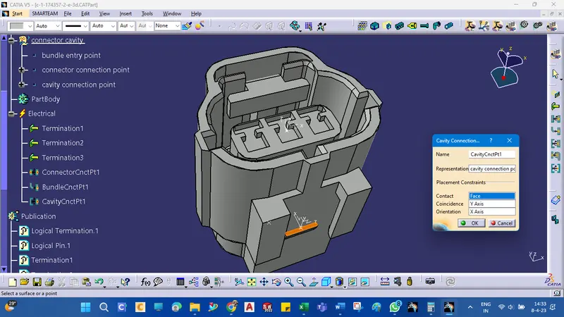
Cavity connection point ( Optional ): This point is used to define the connection of a connector to a connector clip. This only applies to connectors that have the mounting feature for a connector clip.
Connectors_1: Deutsch DT06-08SA
1. Import the downloaded step or .igs file into the CATIA mechanical part workbench.
2. Define the Bundle Entry Point.
3. Define the Connector Connection Point.
connector connection point creations
bundle connection point creations
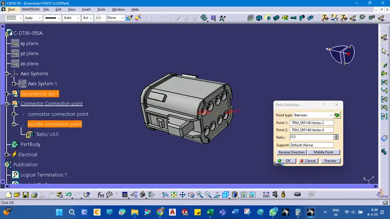
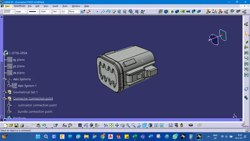
connector connection axis to fix the other connection properly
Define Connector Connection Axis. Y-Axis should face the other mating part/direction and the X-Axis direction should be in match the lock side.
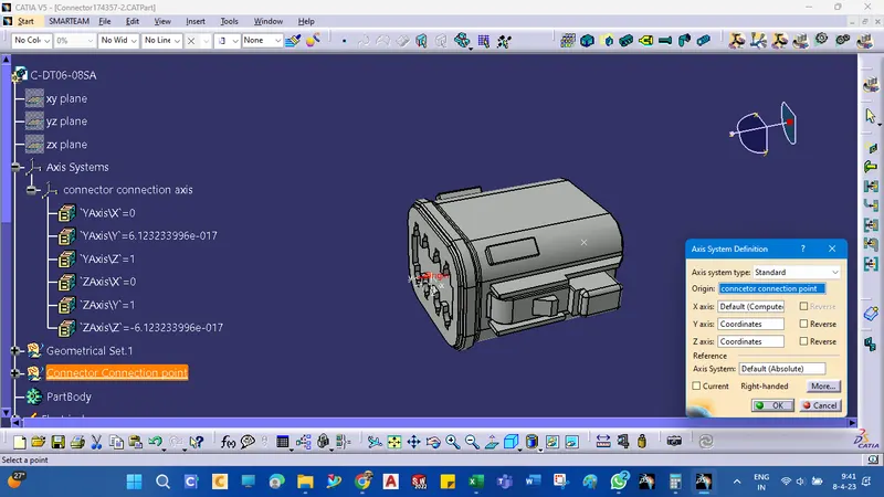
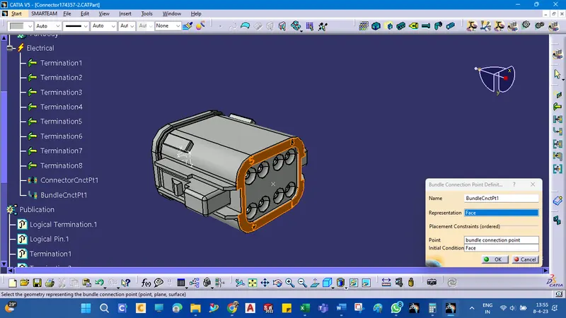
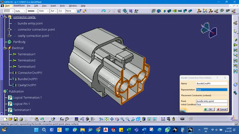
Define the Bundle Connection Point.
Face as Representation, Bundle Entry Point as Point, and Same Face as Representation for Initial Condition.
Define mechanical components to Electrical components
switch to the Electrical Part Design Workbench and define the connector using Define Connector Command with Name and No. of Terminals.
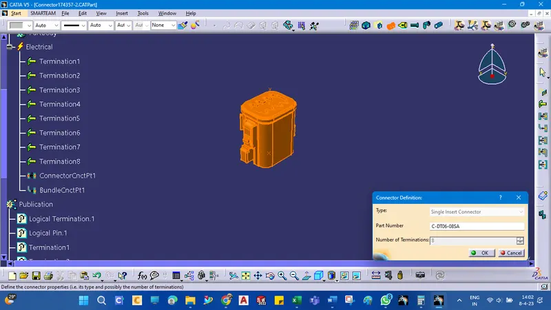
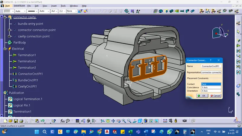
Define the Connector Connection Point.
The connector Connection Point is Representation, Mating Face is Contact, Y - the axis is Coincidence, and X-Axis is Orientation.
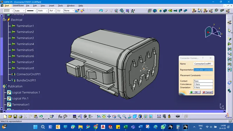
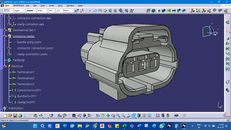
Tyco 174357-2
Define Bundle Entry Point,
Connector Connection Point, and Connector Connection Axis ( Y - Axis facing mating part/direction & X - Axis facing lock ).
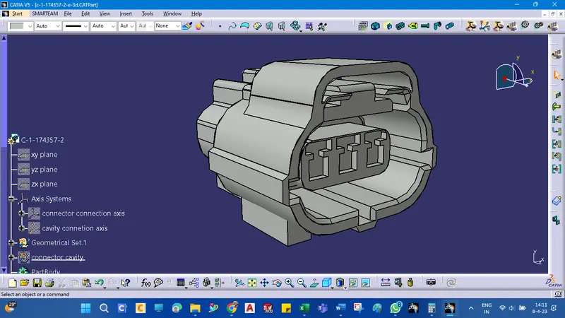
For this type, a connecter needs to be created tree point in order to assembly with the mounting components
connector connection point
bundle connection point
cavity connection point
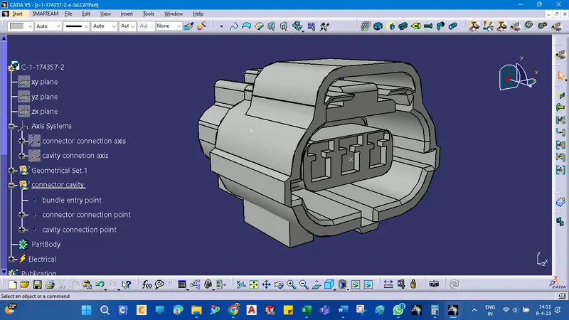
This connector has a Clip / Mounting Cavity. So, define the Clip / Mounting Cavity Point and Clip / Mounting Cavity Axis ( Y - Axis facing mating part/direction & X - Axis facing lock ).
Define as a connector,
Bundle Connection Point, and Connector Connection Point.
CONNECTOR CLIP Tyco 85229-1 :
1. Import the downloaded step or .igs file into the CATIA mechanical part workbench.
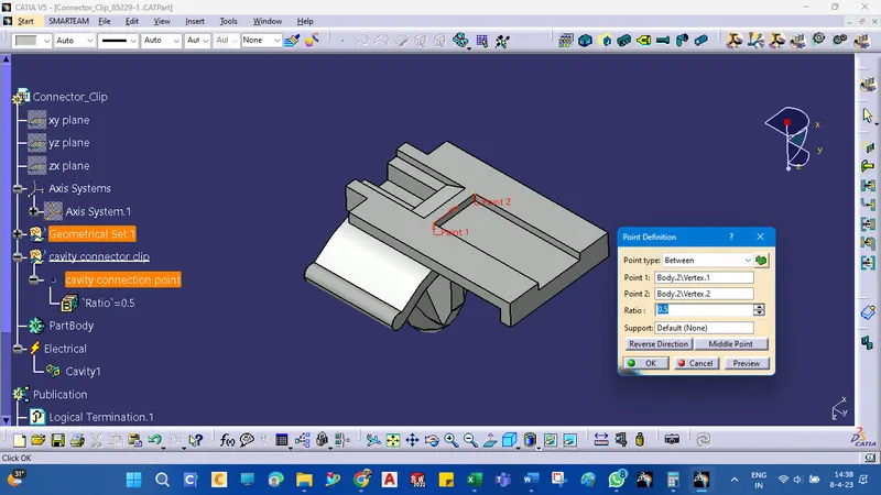
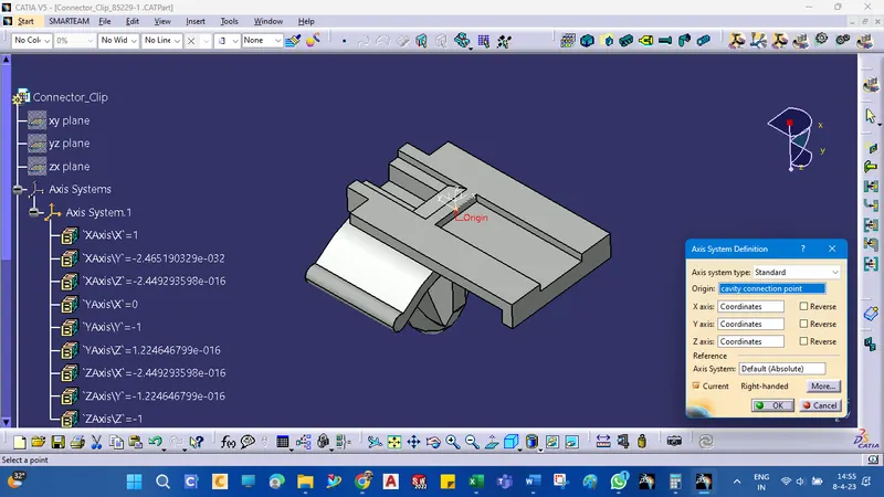
2. Define the Clip / Mounting Cavity Point and Clip / Mounting Cavity Axis ( Y - Axis facing mating part/direction & X - Axis facing lock ). The Cavity Axis should be similar to the Connector Cavity Axis for the correct assembly of the parts.
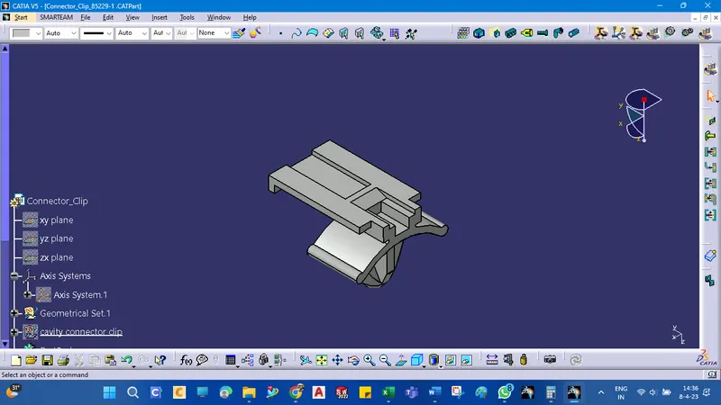
point creations command using by between options and create the point for the cavity connection point
Coordinate-system creations
Change to an Electrical part
defined as a cavity
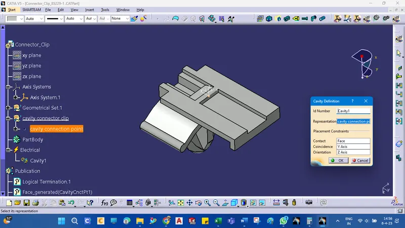
cavity connection point defined
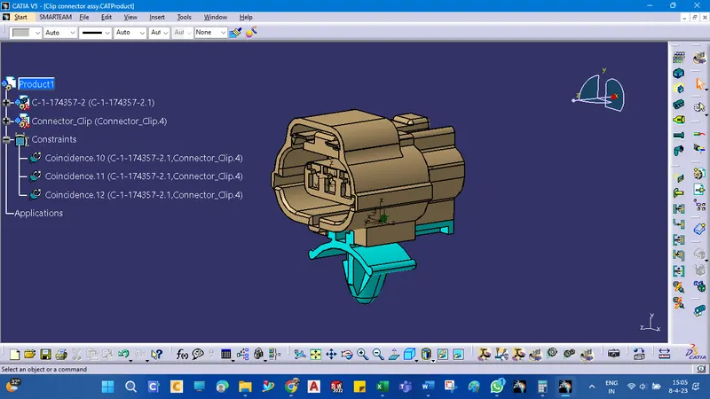
CLIP and CONNECTOR ASSEMBLY
1. Import both the parts in the Electrical Assembly Design workbench and align them properly.
2. Using the Connect Electrical Devices command First select the Mounting Clip and then Cavity Connection Point will show on the Connector in green color automatically.
3. Select the Highlighted green point and the parts will assemble together automatically in the correct position with respect to the defined Connector Cavity Axis on both parts.