Wiring harness design in CATIA V5 - 3D modeling Week 2 Challenge
Ans 1
Objectives
- Downloading the following connectors & Connector clip cad data from the given link
- Defining the Electrical Connector using the Electrical Part Design Workbench
- Defining all the necessary properties of Connectors & Clip
catalog
It is a document that keeps a list of references of other Catia parts and features which we can use these part whenever required.
Step 1
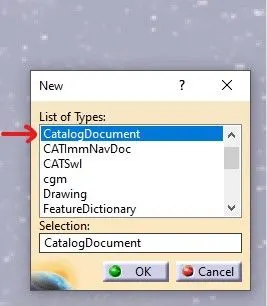
Clicking the New option present in the file tab and using the CatalogDocument in the new option to form the new catalog file for the same.
Step 2
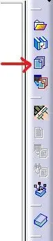
Using the add family option to open the new tab for the creation of a catalog
Step 3
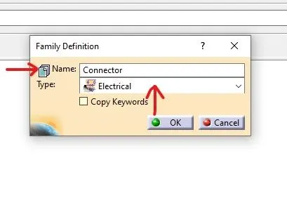
Giving the name of an electrical component for example connector and giving the type in the family definition as Electrical to save our electrical component in this catalog.
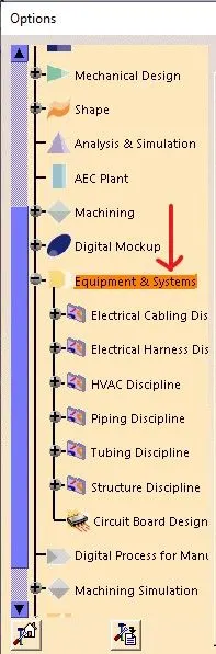
opening the options tool by drop downing the tool option and clicking on the equipment and system to further open the new options.
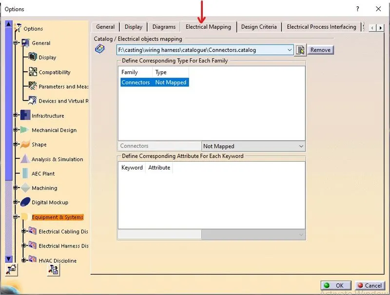
adding the Electrical mapping option to add the already created in the connector catalog.
for the storage of cad parts of electrical components
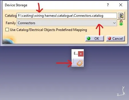
for storing the cad parts the storage option and giving the location of the catalog file in the catalog option and choose the required family in the family tab.
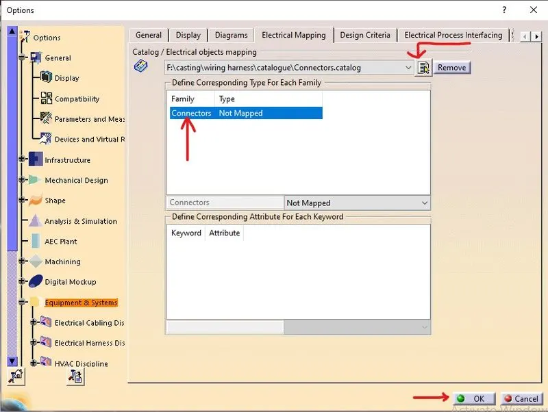
using the add file option in the mapping tab and selecting the required catalog file to add and then clicking ok to get the required catalog for further use in the future.
Connector
It is an electro-mechanical device used to join electric terminations and creates electric circuits.
Deutsch DT06 – 08SA
https://www.te.com/usa-en/product-DT06-08SA.html
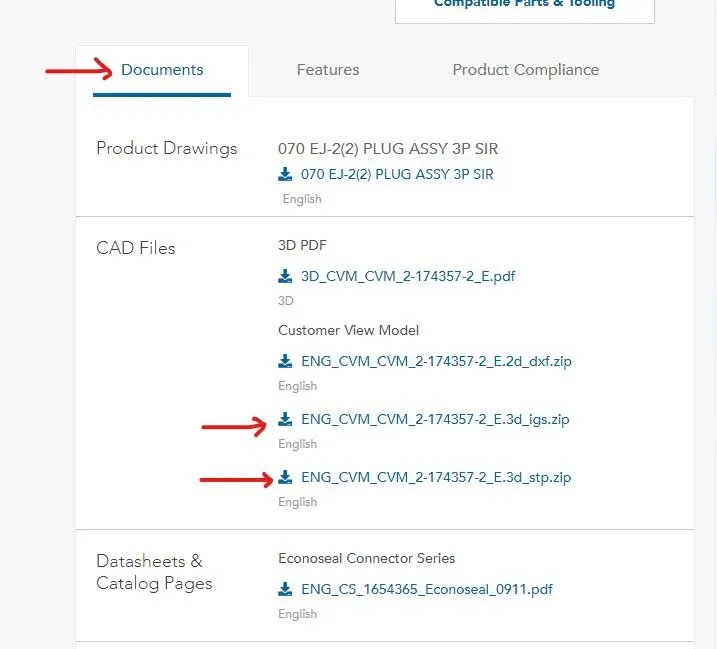
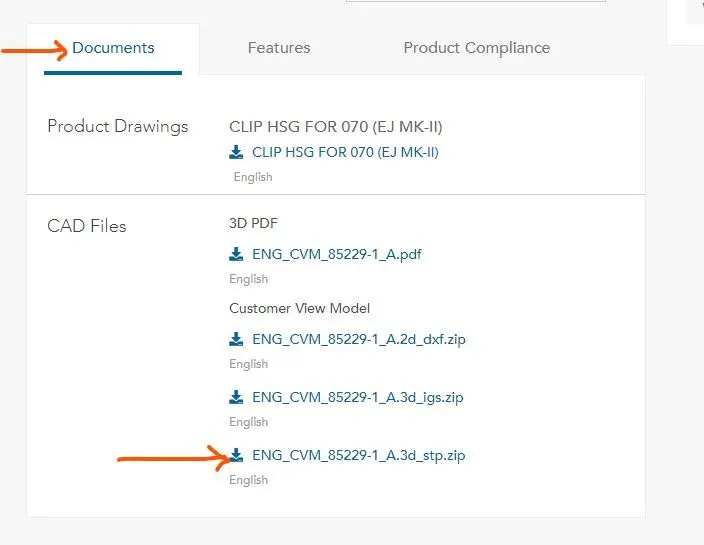
By using the above link we download the required part for our work
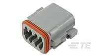
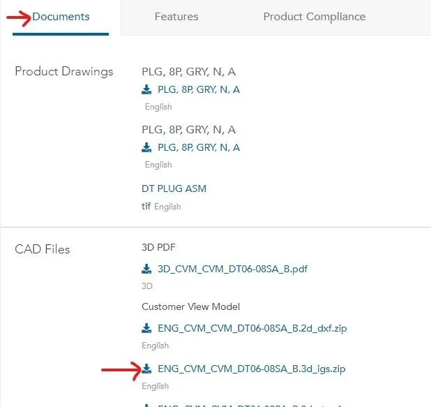
using the documents tab to download the cad file.
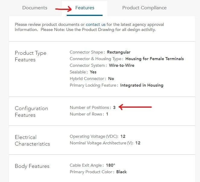
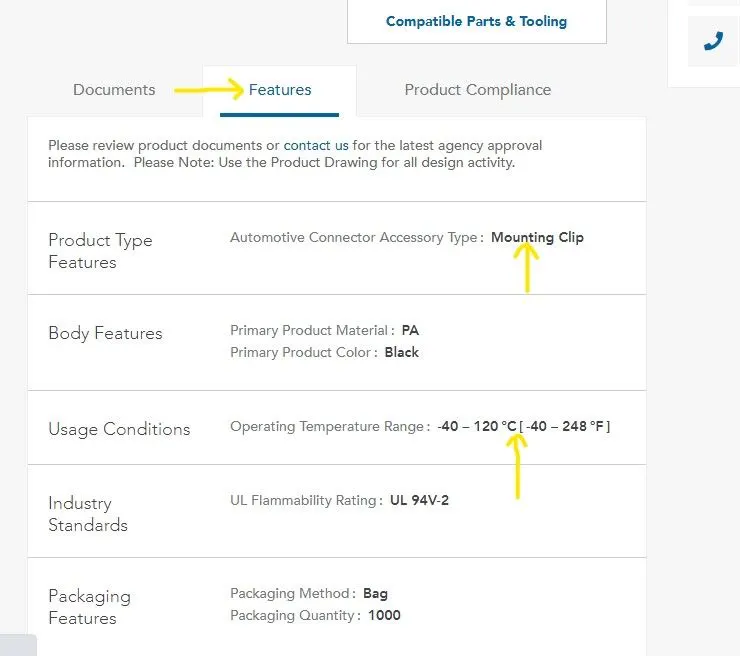
we can also see the properties of the connector before using it in our assembly by using the features option.
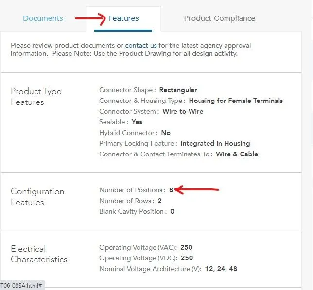
After downloading the required cad file we now move forward with the creation of the various parameters for our connector. For the creation of various parameters, we require the following point in the parts.
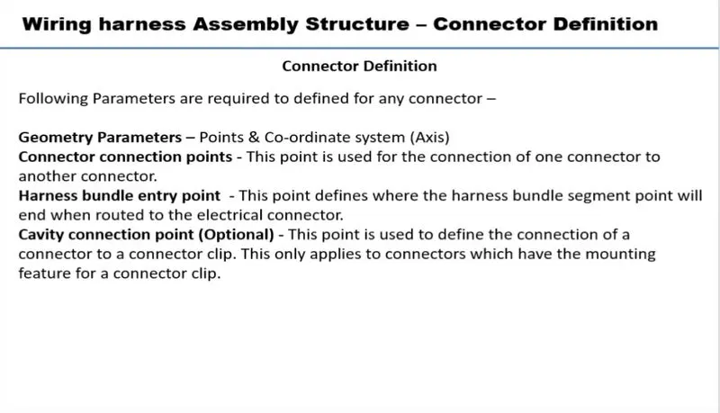
Bundle Connection Point
It is used to connect the wiring harness to the connector
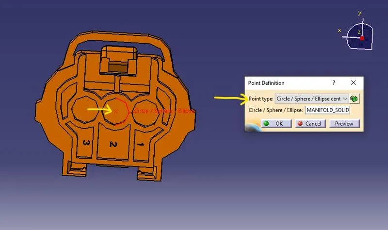
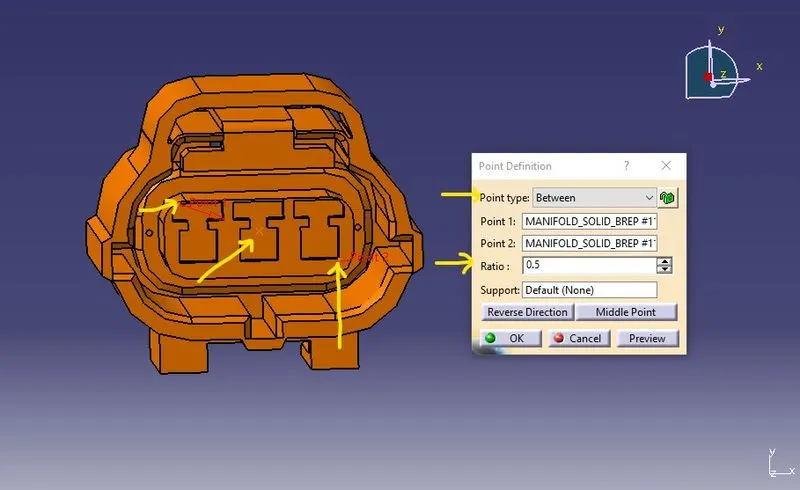
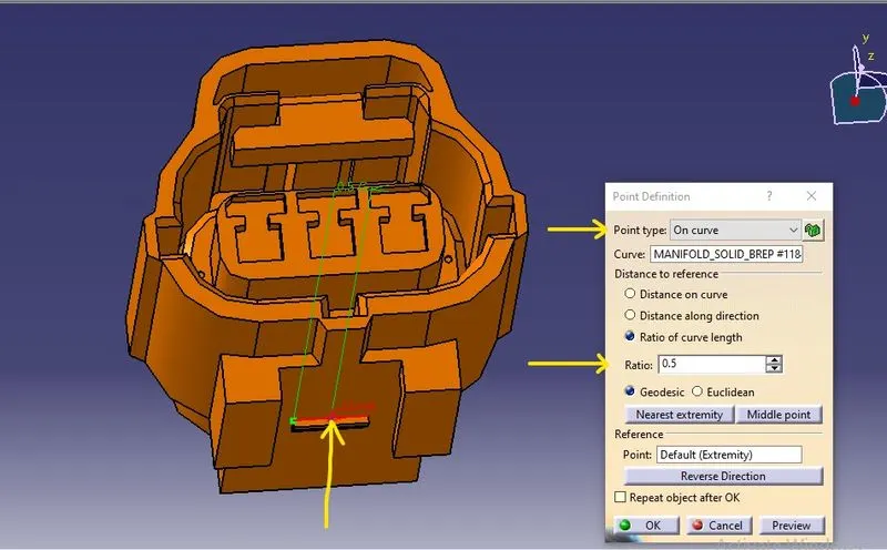
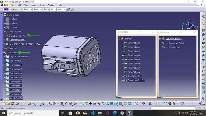
for the creation of the bundle connection point, we create the point at the midpoint of the termination side of the connector.
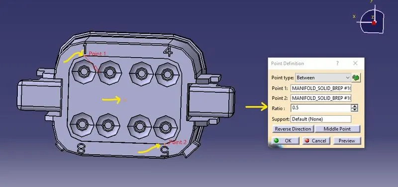
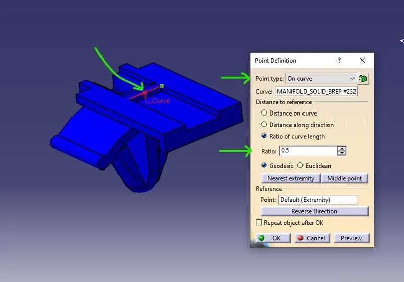
using the between type of point definition to create the point at the midpoint on the face select two points and give the ratio as 0.5 to create the required bundle connection point.
Connector Connection Point
It is used to connect the other device or connector to the main connector
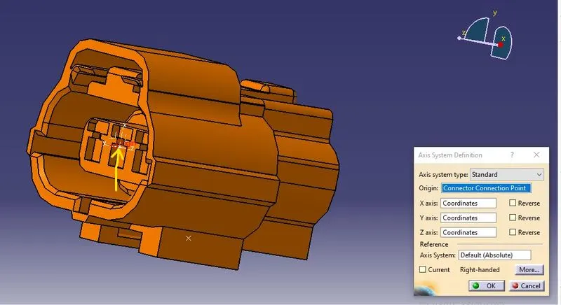
using the same process to create the point at the midpoint at the other face of the connector which is directly opposite to the bundle face.
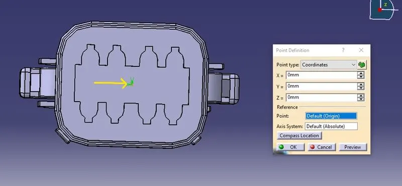
Axis
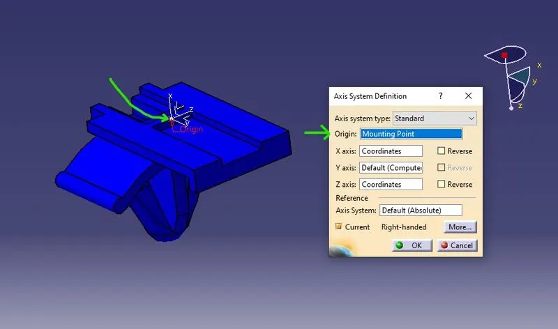
we must create the axis for the proper facilitation or for the proper seating of other parts with the connector.
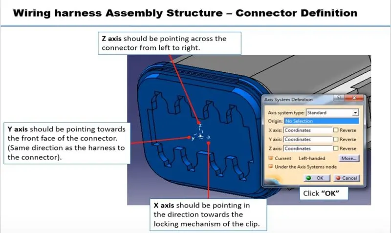
though these are not industry standards we need to be consistent with both mating parts in order to get proper assembly
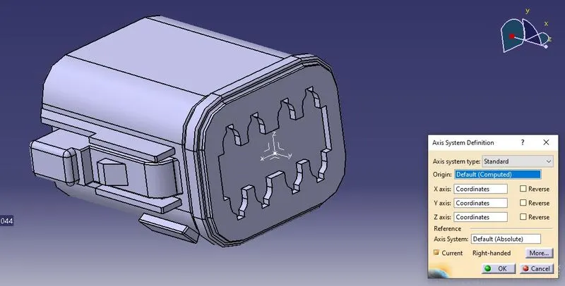
Cavity Connection Point
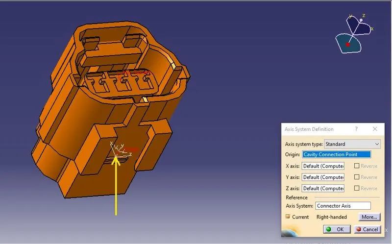
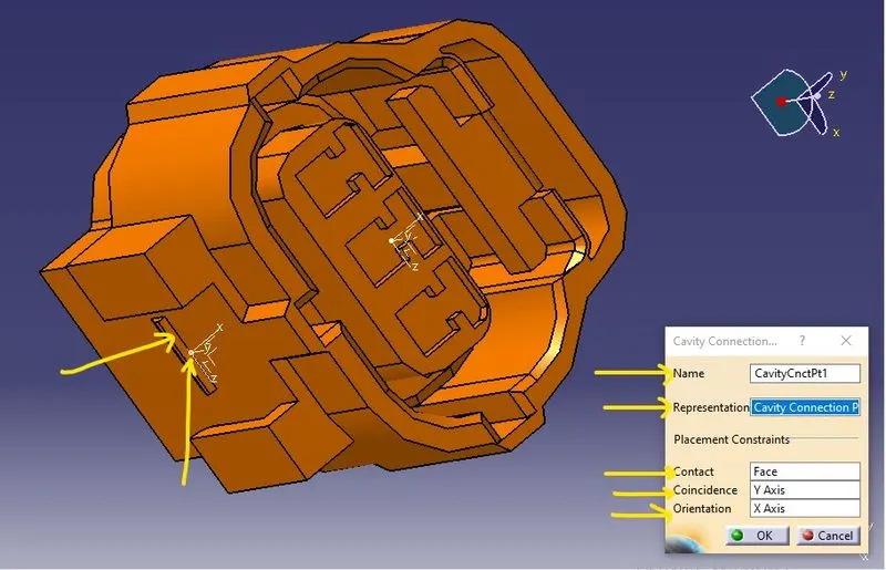
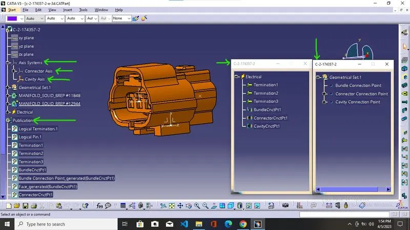
It is used to provide the connection between the mounting system of connector clips with the connector. It is the same as the Connector connection point we also need to create an axis here similar to the connector axis but is an optional point we created it only when we required the mounting part.
After Creating the various parameter required in the connector we now need to convert the mechanical part into the electrical component for this we are going to use the electrical part design workbench.
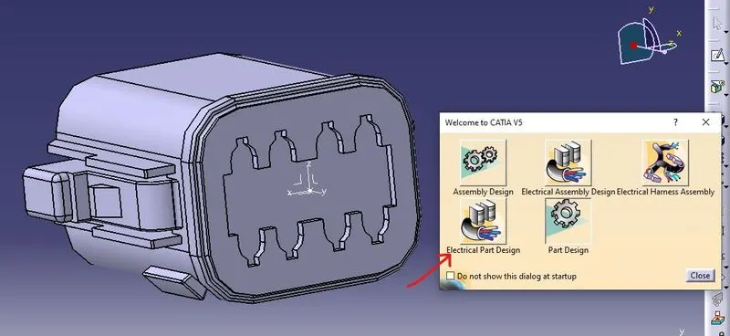
To convert the required part into the electrical component we use the define connector tool option
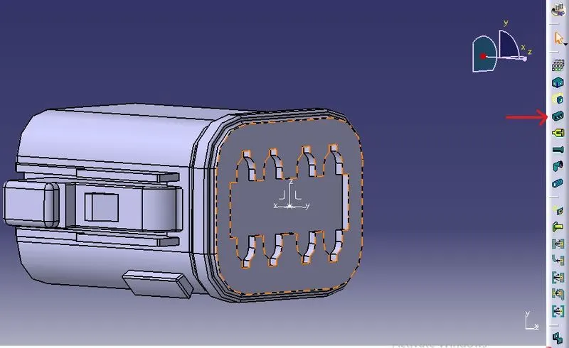
By simply choosing the connector type and the number of terminations we can easily define the part as an electrical connector.
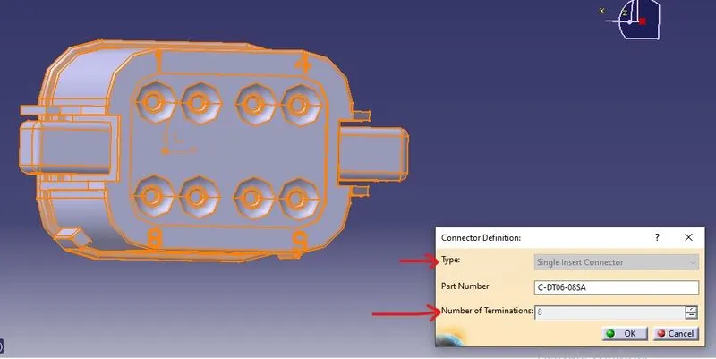
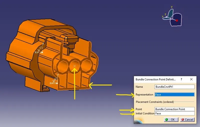
We now need to define the various point we created in the part workbench in the electrical definitions for that we use the bundle connection point to define the Bundle connection
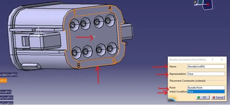
In the representation, we select the face which is normal to the bundle entry in the point we use the bundle point, and again in the initial connection we select the face which is normal to the bundle entry.
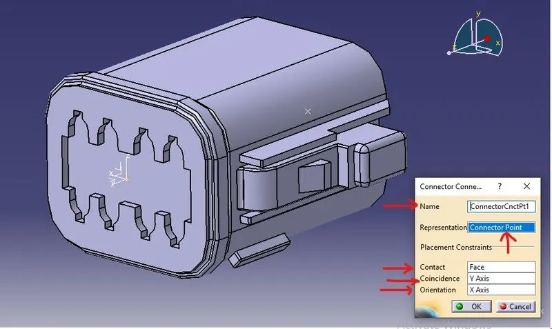
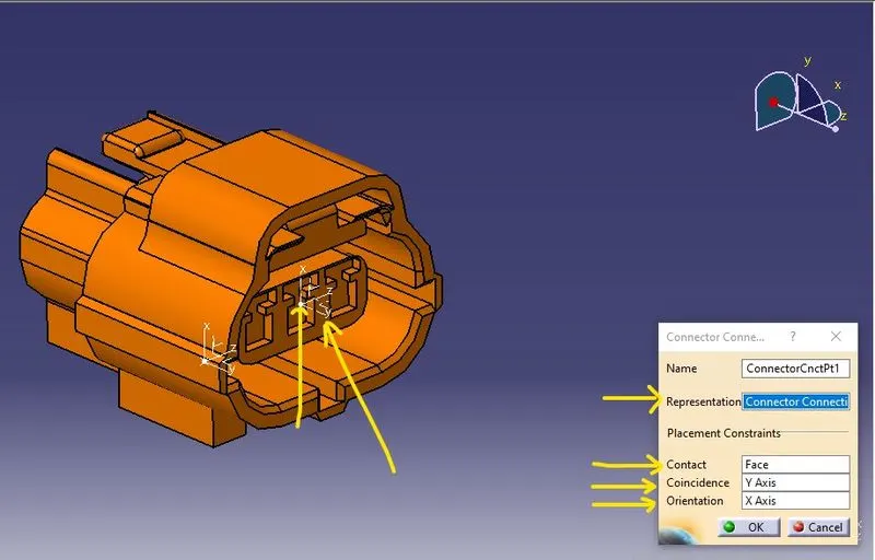
We now need to define the various point we created in the part workbench in the electrical definitions for that we use the connector connection point to define the connector connection
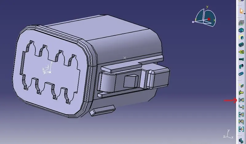
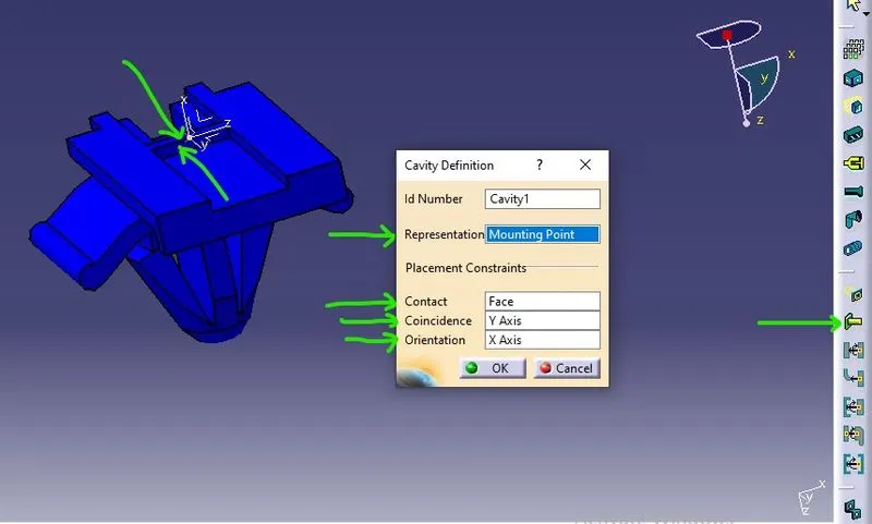
for that, we choose the representation as our already created connection point in the contact we choose which will go to be in contact with other mating parts we choose the coincidence axis as the Y axis where our parts move in and out for the assembly or in case of disjoining the parts and in the end we choose the orientation axis x-axis.
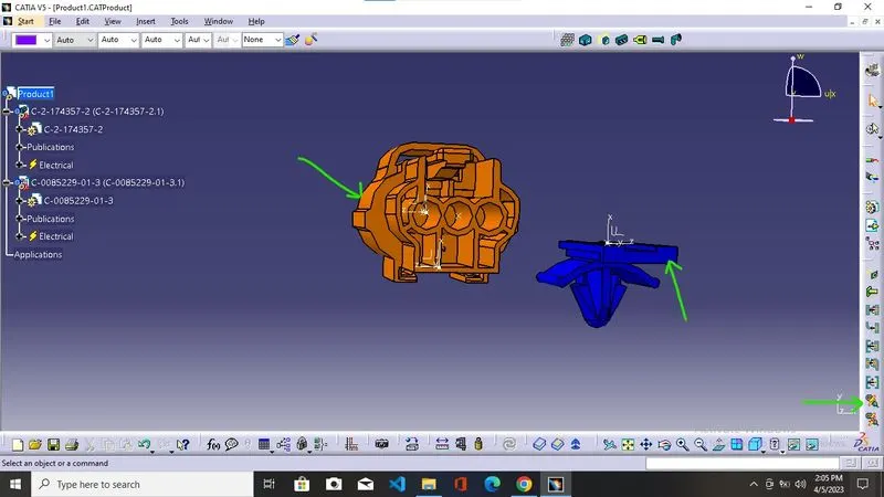
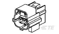
Tyco 174357-2
https://www.te.com/usa-en/product-2-174357-2.html?source=header-match
we follow all the steps as mention above to create the product
Mounting
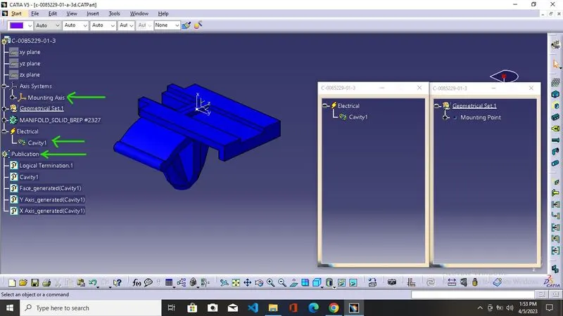
Mounting equipment is a non-electrical part that groups one or more electrical connector parts placed into empty cavities. This object is used to support the placement of all electrical devices and to mount them together. For instance, mounting equipment can represent a rack or an electrical panel.
Tyco 85229-1
https://www.te.com/usa-en/product-85229-1.html?q=85229&source=header
In order to convert it into electrical equipment first we need it to define as mounting equipment in the electrical part design workbench
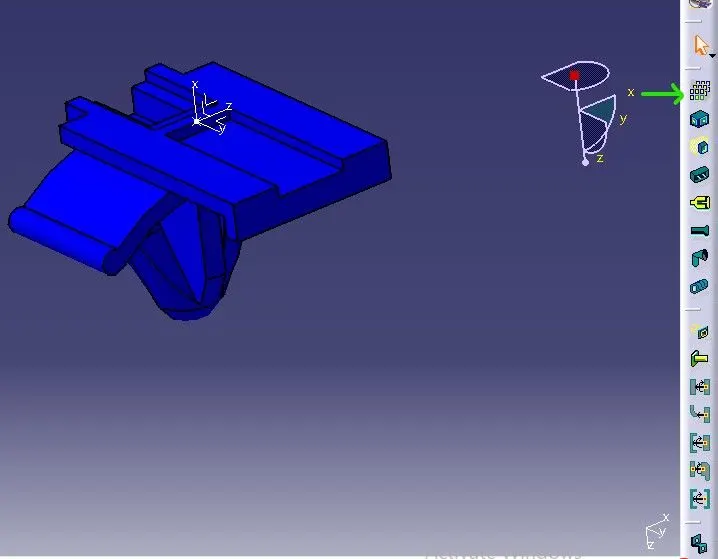
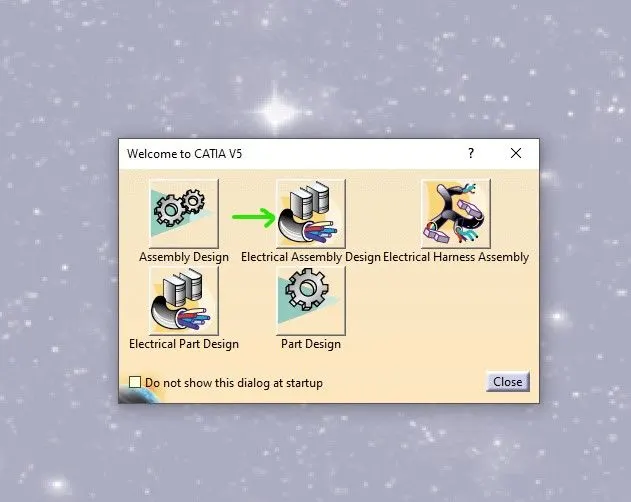
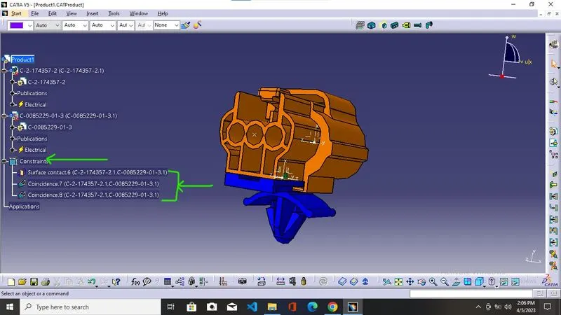
For the assembly of electrical components we electrical assembly design workbench