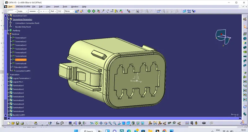
Wiring harness design in CATIA V5 - 3D modeling Week 2 Challenge
- CONNECTOR TYCO 174357:
- First we downloaded the part and open it in CATIA V5
- Created Geometrical Parameters: Switch to part design and create a bundle connection point on the wire entry side at middle of the face as shown in images(1) and a Connector connection point on the other side of the connector at the middle where another connector will mate there. Now created an axis system on this point where y axis normal to the connector face, x axis towards the locking mechanism, z axis either side as it is see image(2). Make sure that the mating parts must same axis at it is here. WE will create same axis point as discussed above for the cavity connection image(2a)
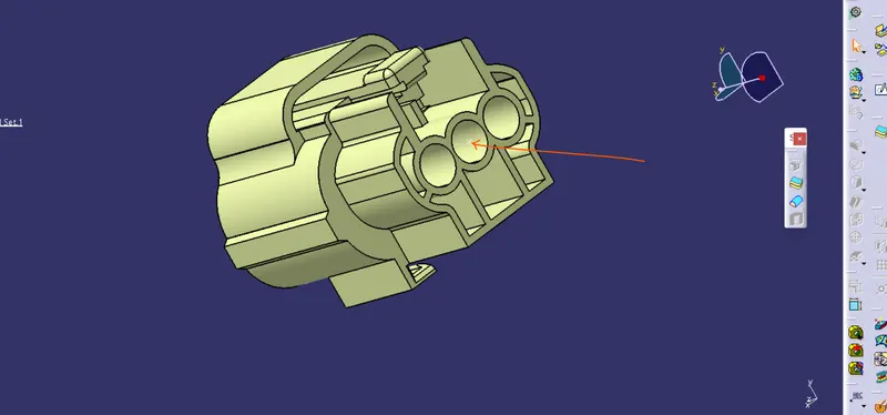
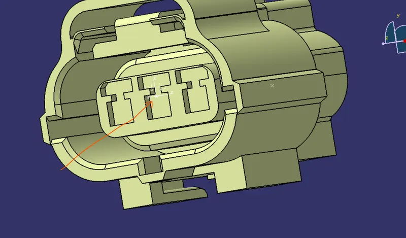
image(1) image(2)
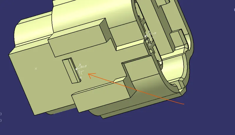
image(2a)
3. Now i have defined it electrically for this i have to switch to ELECTRICAL PART DESIGN , Go to DEFINE CONNECTOR image(3)>click on part and give no. of wire entry hole we have image(4)
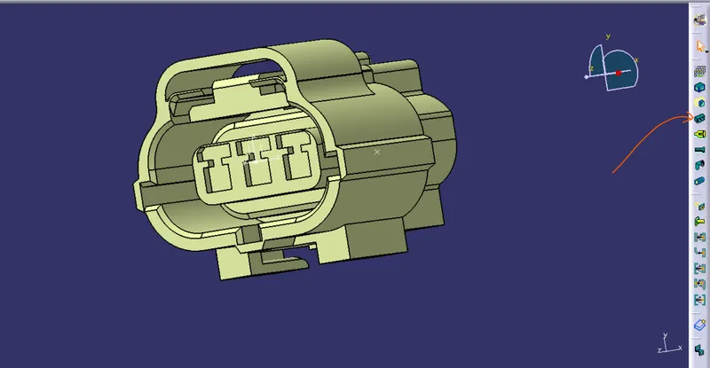
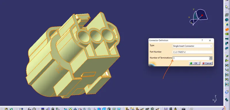
image(3) image(4)
4. Now we will defined bundle connection point for this clik on DEFINED BUNDLE CONNECTION POIN image(5)>click on part>a popup window open and select as defined in image(6)>ok.
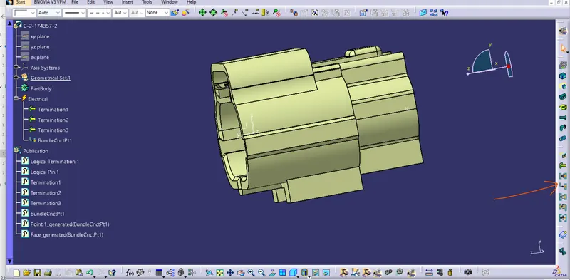
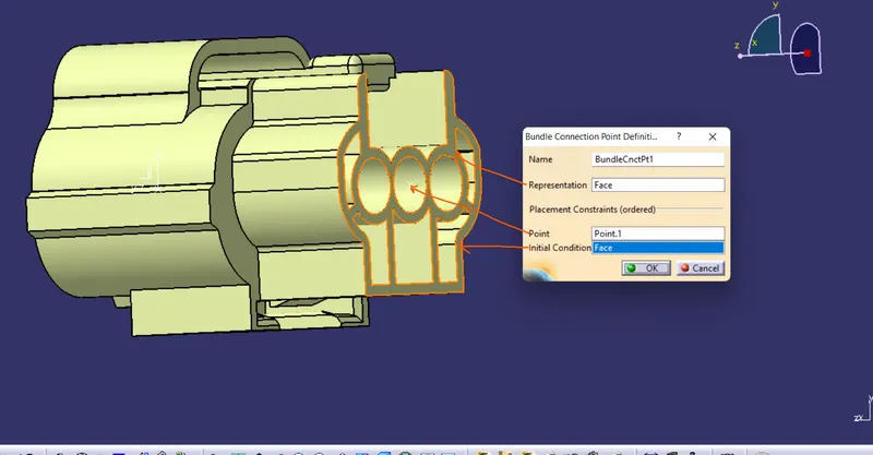
image(5) image(6)
5. We wiil defined now Connector connection point for this go to command DEFINE CONNECTOR CONNECTION POINT image(7)>click pn part> a popup window will open and select all parameters as defined as in images (8)
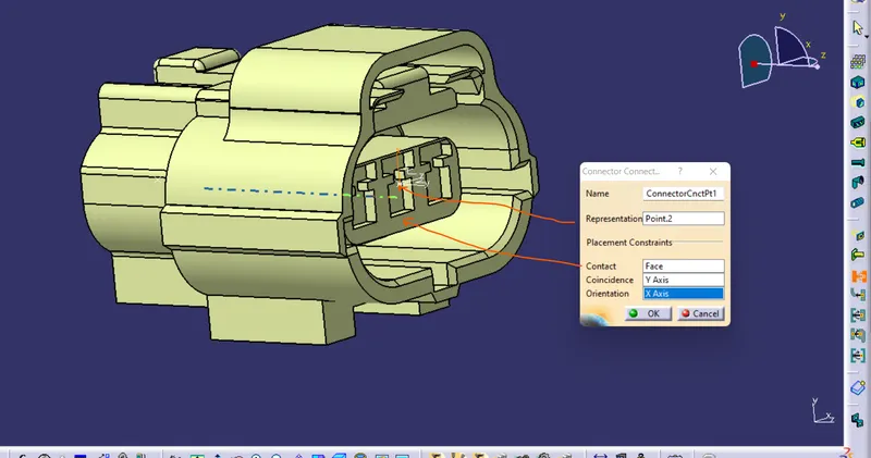
image(7) image(8)
6. Now we will defined cavity connection point for this go to the command DEFINED CAVITY CONNECTION POINT image(9)>click on partn now here same window will appear as connector connection point select all as shown in images(10)
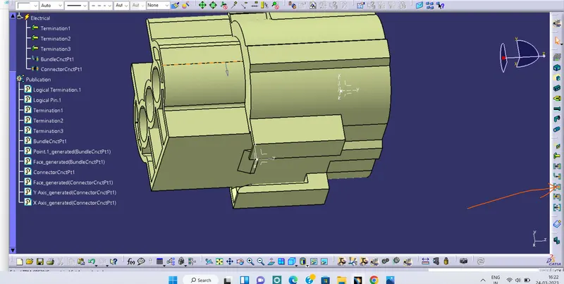
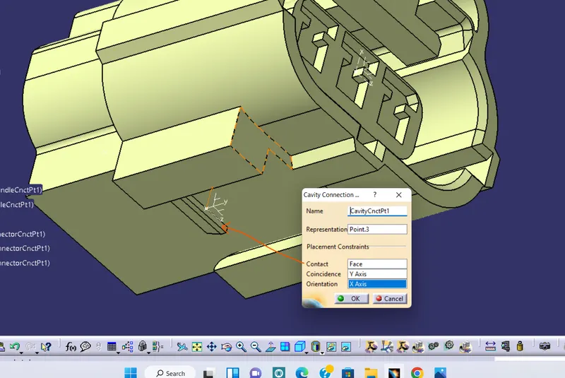
image(9) image(10)
- Now for mounting:
1 open in ai CATIA V5
2 Create geometrical parameters: Create point and axis system as same as we have created in the connector shown in image (11)
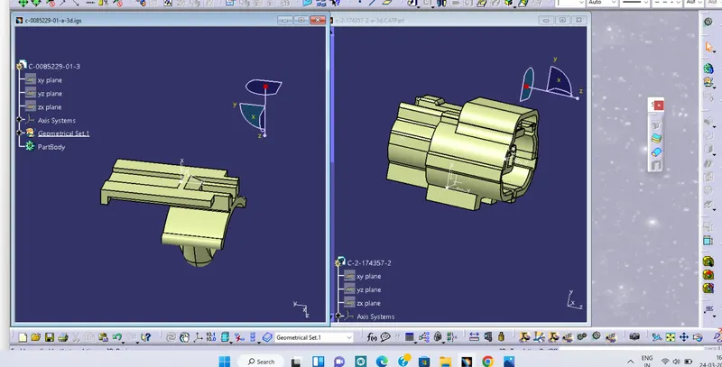
Image(11)
3 Switch to ELECTRICAL PART DESIGN > go to command DEFINED MOUNTING EQUIPMENT image(12)>Click on part >ok
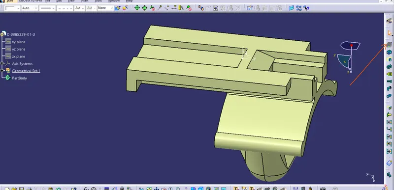
image(12)
4 Go to Defined cavilty image (13)>click onn part> a popup window will open select a sown in image(14)
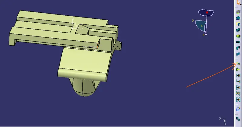
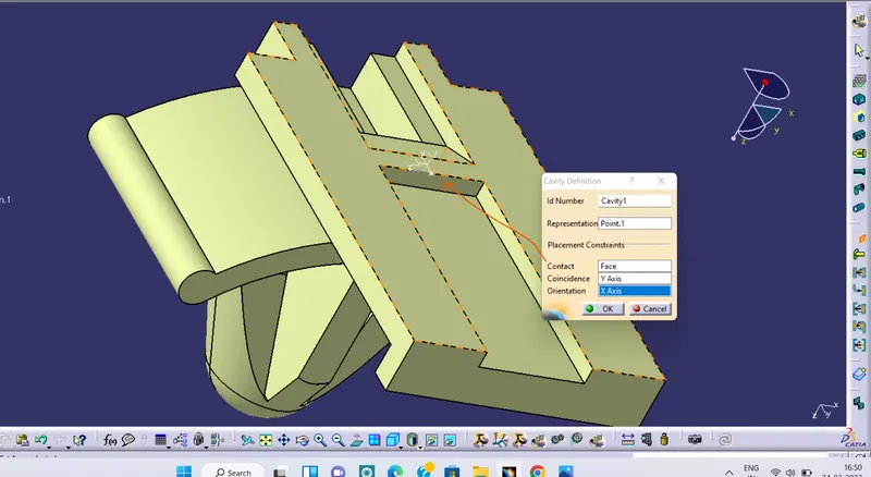 .
.
image(13) image(14)
- NOW for assambly follow the steps:
1 we will switch to electrical assambly design
2 copy the connector and mountings and paste it in assambly design.
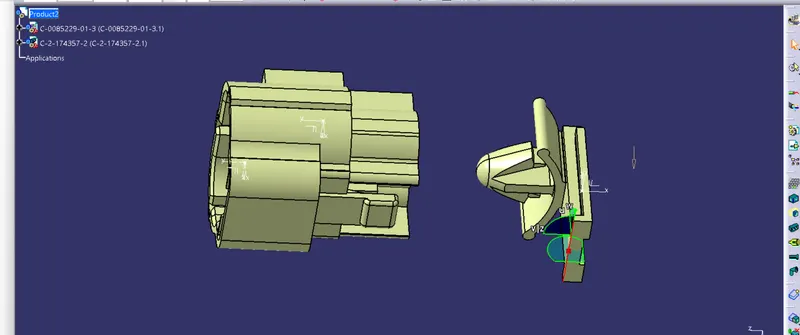
3 Drag the part in the same orientation where it going to meet
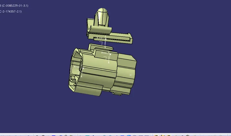
4 Go to CONNECT ELECTRICAL DEVICES > Click on connector and cavity both to met them
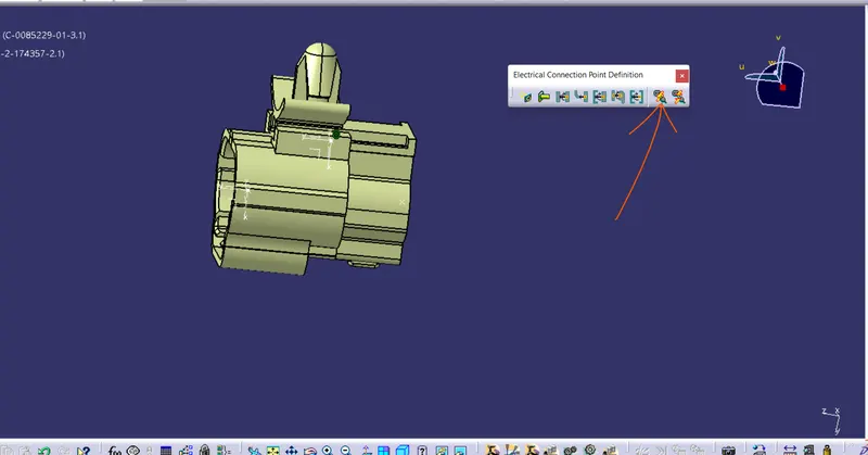
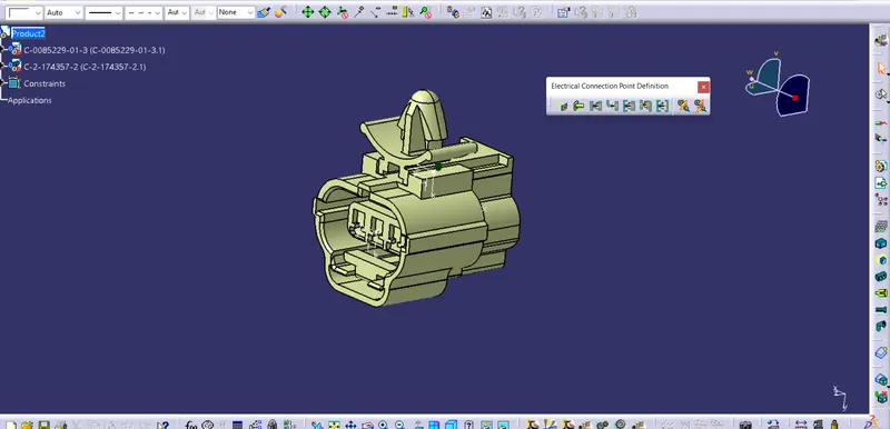
- CATALOG CREATION:
For creating catlogue go to file>new>catalogdocument>ok image(15)> a window will popup>add family image(16)>give name, element : electrical image(17)>ok>file>save image 18>close the window
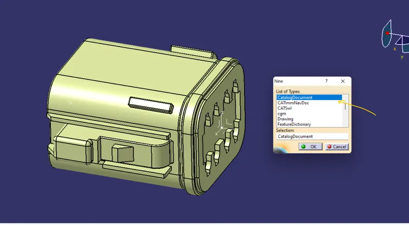
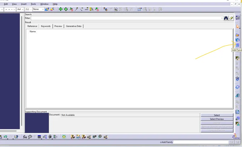
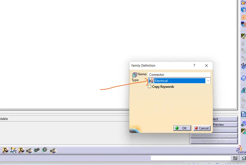
image 15 image16 image17
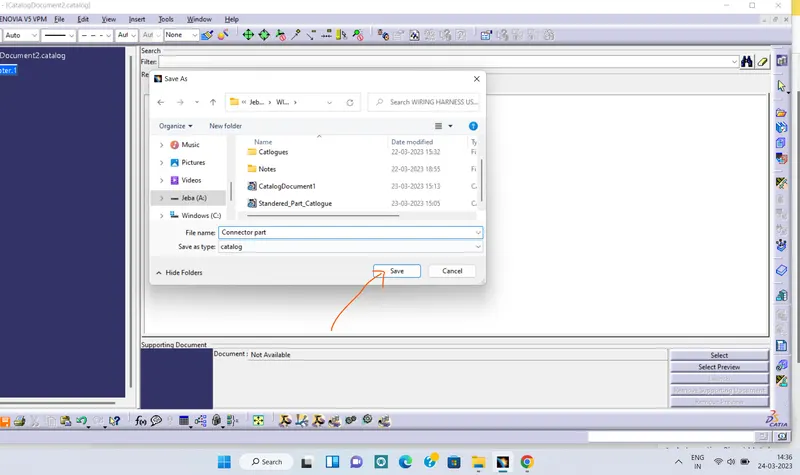
image18
Now go to tool>option>infrastructure>catlog editor>click on file shown in images add favourite(19)>now select the part from the folder you want to add image(20), a file will be added image (21)>ok
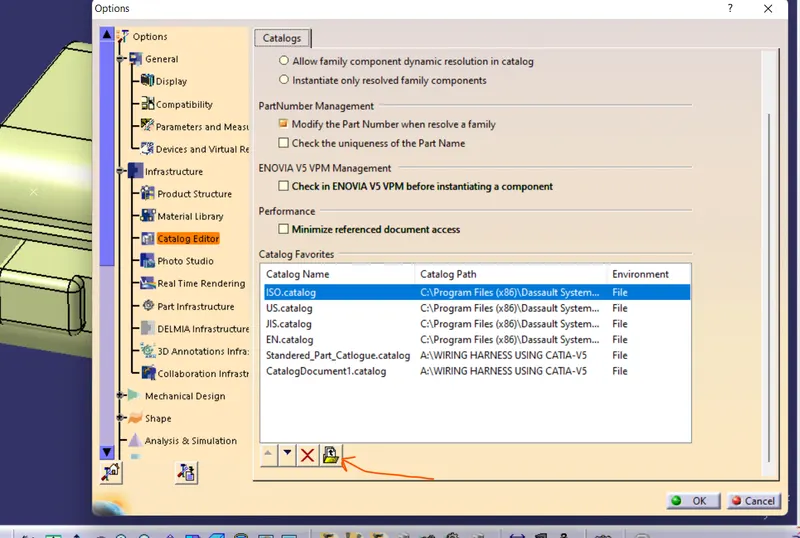
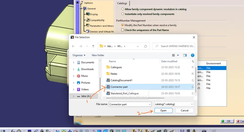
image 19 image20
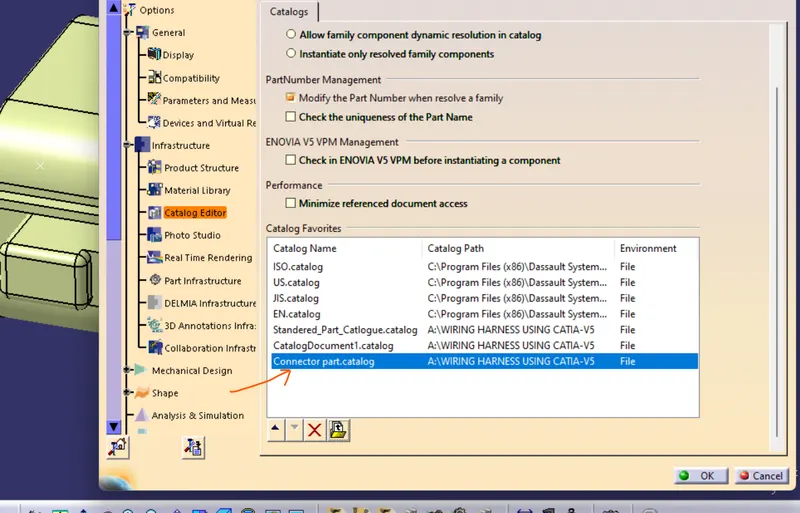
image 21
Now to add part in Catlog go to tool> option>equipment and system>click on attachement image(22)> coose the catlog file you have created and press ok image(23)
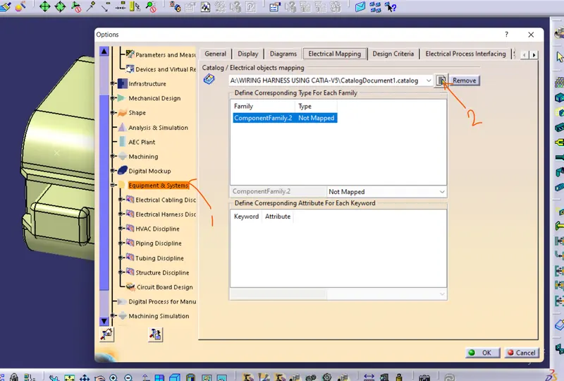
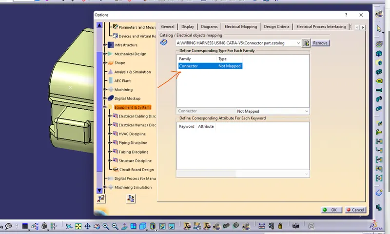
image(22) image (23)
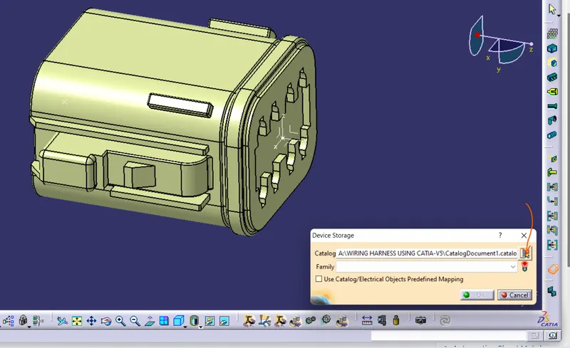
Now go to ELECTRICAL PART DESIGN>STORE DEVICE image(24) >click on calog file attachementimage(25)> choose catlog file>
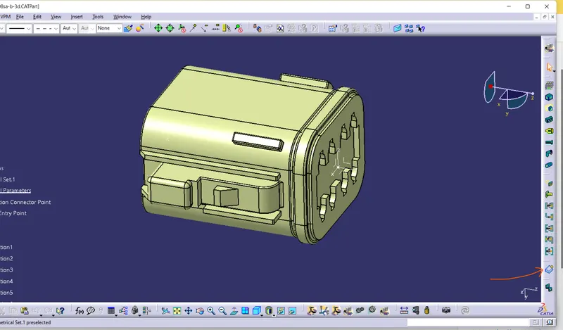
Similarly we have defined the below shown part elecrically