Wiring harness design in CATIA V5 - 3D modeling Week 2 Challenge
ans. first i have to download two connectors and aone clip from the given files.
after downloading it from the files i have to extract the files .and then i have to define this electrically
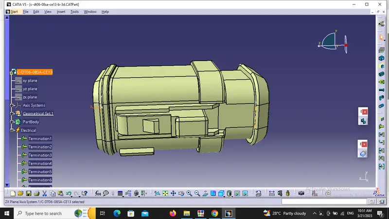
this is DT06-8SA connector..
for defining this conncetor electrically i have to go to part design workbench to give point and to both the connector side as well as bundle entry side.
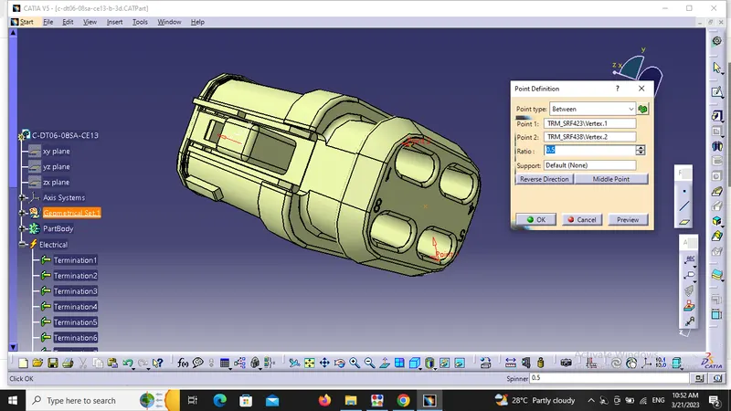
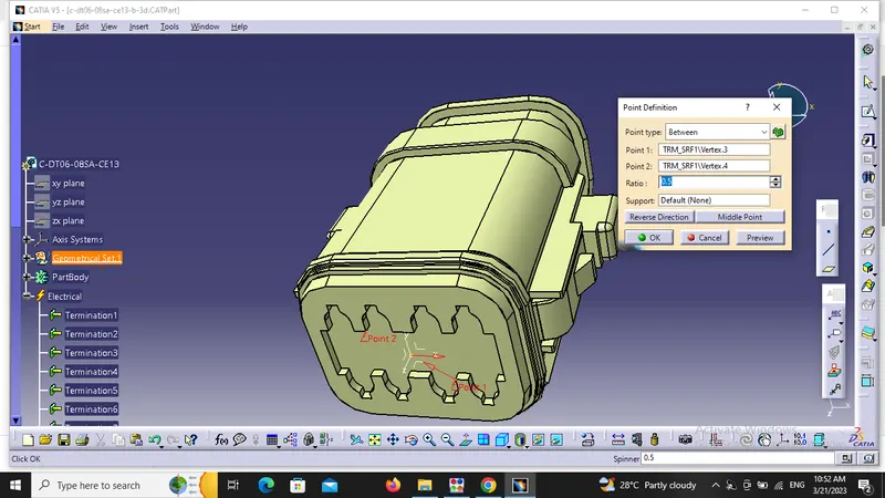
After defing the points we have to define the axis on the mating side of the connector(every connector has two side 1 is mating side and 2 is bundle entry side).
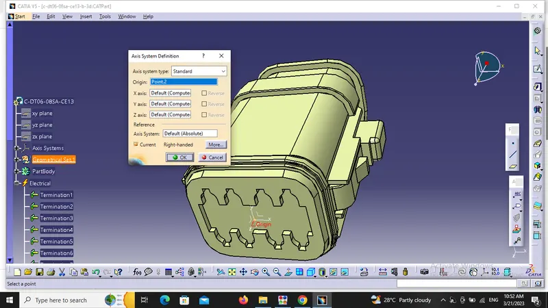
so this part workbench is done here. now we have to switch to elctrical design workbench to define it as connector , and define connector connection point and bindle connection point.
no. of terminations are 8
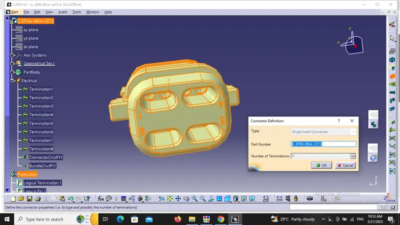
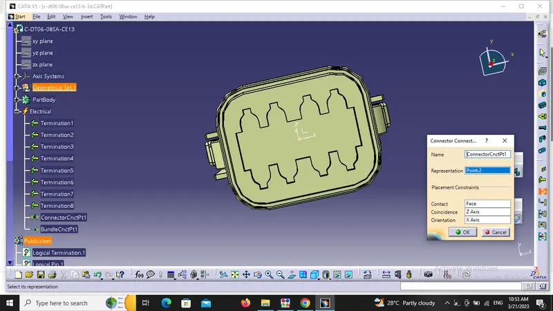
the representation on mating side is always the point. the contact should be the face. and coincidence is alyways that axis which is coming outwards. and the orientation can be anyone from the left two axis.
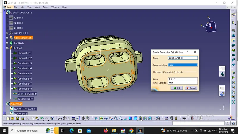
in bundle entry side, the representation shoul be face and initial condion is same as representation.
then we are defing the secong connector Tyco 174357-2
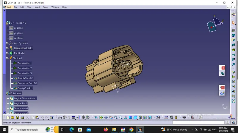
procedure is same for all he connectors but some commands are additional related to the type of connector.
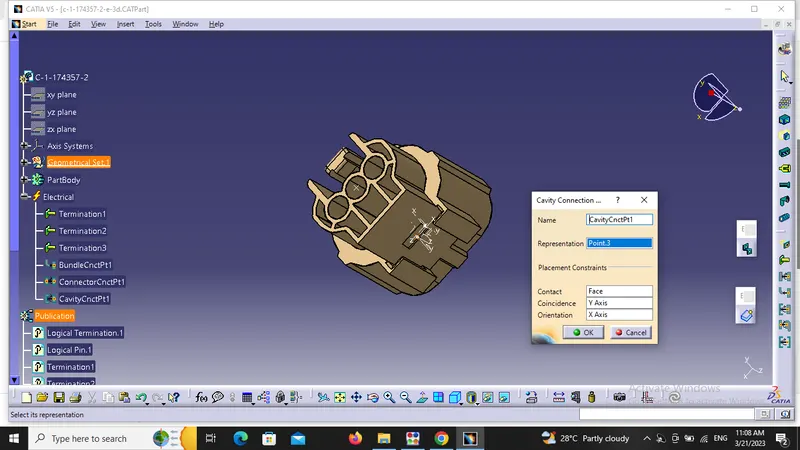
so first we are in partdesign workbench and we have to define the points on both side of the connector. after thst we hav to define the axis on mating side of the connector. but this connector cn include a cavity as well so it has a cavity connection side also. so we have to define point and axis at cavity side also and make sure that the axis in this connector at cavity side should be same as the axis in the cavity clip for proper connection.
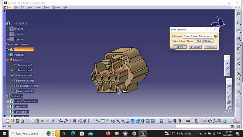
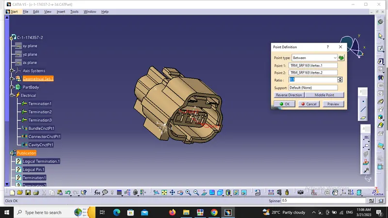
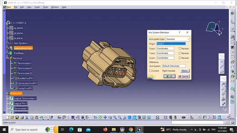
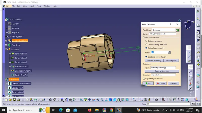
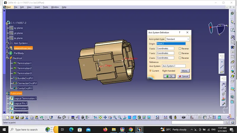
now we have to switch to electricalpart design to define the commands like connector,connector connection point, bundle connection point and cavity connection point.
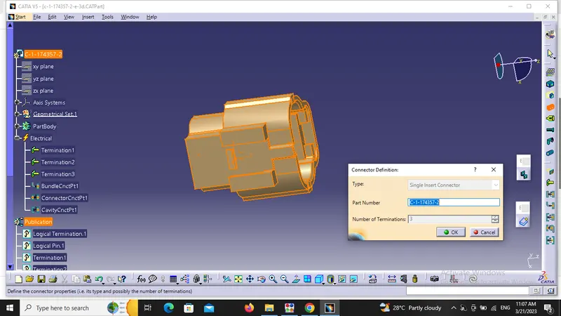
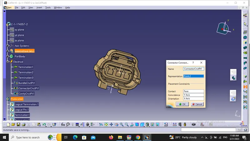
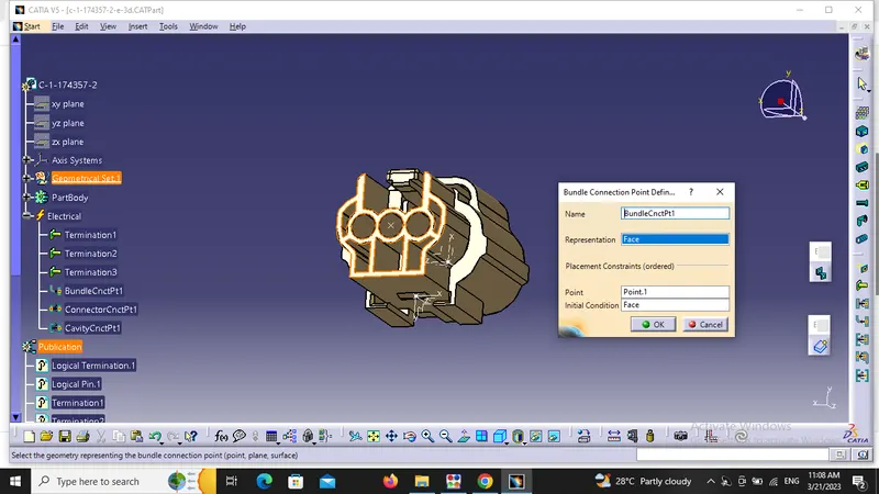
ffor cavity connection point the representaion should be point , contact should be face, coincidence and orientation should be same as the cavity clip coincidence and orientation.
now we have to define the cavity clip Tyco 85229-1.
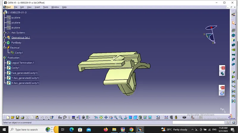
in this we have to define the point and the axis from part design workbench(axis should be same like the cavity side of the connector).
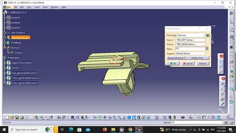
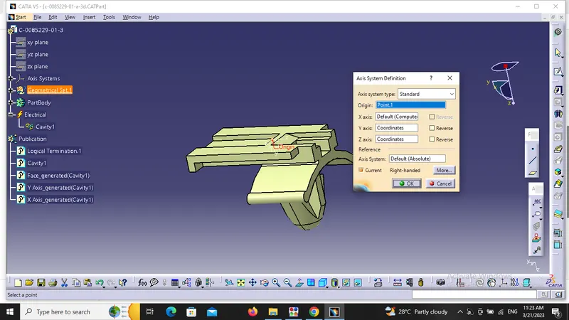
after this we have to switch to electrical part design workbenchdesign workbench and defining it as a mounting equipment by using mounting equipment command. because we are mounting the cooector with the help of a clip . first click the command,then click on the connector in the tree to make use of the command
after that we have to use define cavity command.
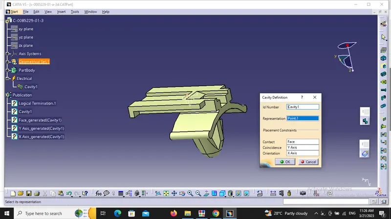
Now we have to mouth the conncetor on the clip. it can be done by using electrical assembly design workbench. we have to use connect electrical devices command to make it happen.
first we have to make a new product from the file option and then we have to copy paste the cooector and clip into that product to mount them.
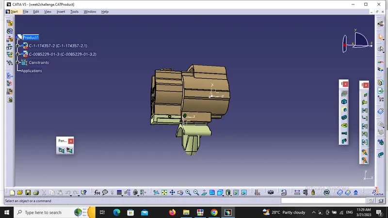
we can use connect electrical devices command by selecting the coomand first and then we have to select cavity and the connector one by one to mount them.