Wiring harness design in CATIA V5 - 3D modeling Week 2 Challenge
WIRING HARNESS DESIGN 3D MODELING WEEK 2 CHALLENGE
TITLE
Defining Connectors and Clips using CATIA V5
OBJECTIVE
Downloading the 3D CAD files form the te.com website and then defining the parts electrically and further creating a
catalogue for the components.
INTRODUCTION
A connector is a device(or more precisely, a mating pair of devices, often a plug and a socket) for connecting together two
or more wires, cables, or hoses, allowing electricity or fluid to flow but also allowing easy disconnection and reconnection
when necessary.
Mounting Clips are used for supporting conduits. These clips are made of High Quality Impact Resistant Polyamide. The
mounting clips are stackable and are fixed with the help of screws on to the panel or equipment surface.
SPECIFICATION
Connectors:- 1. Deutsch DT06 – 08SA
2. Tyco 174357-2
Mounting Clip:- 1. Tyco 85229-1
DESIGN METHODOLOGY
Deutsch DT06 – 08SA
First open the 3D CAD data in Catia and then convert the file format(ex: .igs,.stp) to .CATPart.
-- Then define the connector geometrically in the Catia Part Design Workbench. To do that we have to first assign a mid-
point to the bundle connection side face of the connector and then we also have to assign a mid-point to connector
connection side of the connector, along with that we also have to assign an axis system on the mid-point of the connector
connection side face. This will allow us to fully define our connector geometrically.
-- After that start the Electrical Part Design Workbench in Catia to define the connector electrically.
-- First we select the define connector option from the toolbars and then we select the connector body and also assign
the number of terminals to the connector which in this case are 8 terminals.
-- Then we select the define bundle connection point option from the toolbars and then we select the connector body,
bundle contact face for representation, mid-point for point, and again bundle contact face for initial condition and then
click on ok.
-- Lastly we select the define connector connection point option from the toolbars and then we select the connector body,
mid-point for representation, contact face for contact, Y-axis for coincidence and X- axis for orientation and then click on
ok. This will fully define our connector electrically.
-- Save the file.
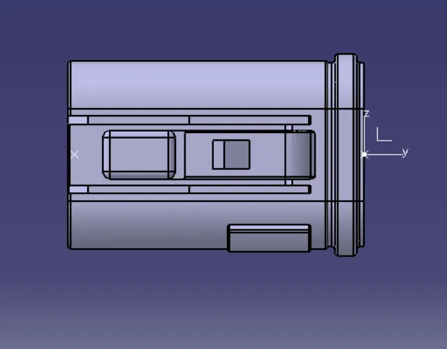
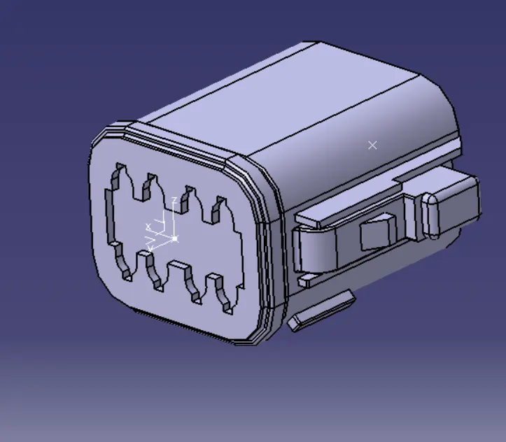
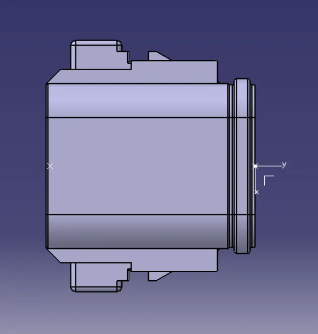
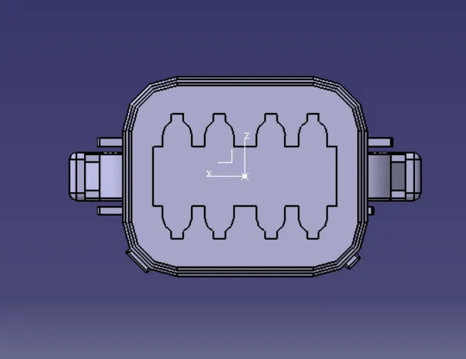
VIEWS OF Deutsch DT06 – 08SA
SIDE VIEW
ISOMETRIC VIEW
TOP VIEW
SIDE VIEW
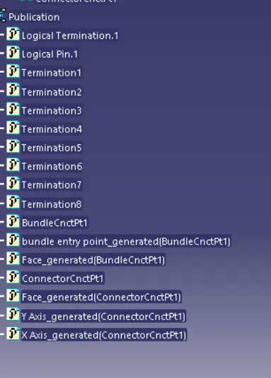
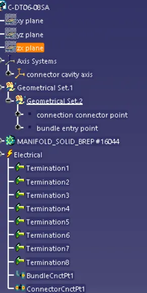
TREE STRUCTURE
Tyco 174357-2 & Tyco 85229-1
For connector:
--First open the 3D CAD data in Catia and then convert the file format(ex: .igs,.stp) to .CATPart.
--Then define the connector geometrically in the Catia Part Design Workbench. To do that we have to first assign a mid-
point to the bundle connection side face of the connector and then we also have to assign a mid-point to connector
connection side of the connector, along with that we also have to assign an axis system on the mid-point of the connector
connection side face.
--Also we have to create a mating reference at the bottom side of the connector so that we can mount a clip onto the
connectors. To do that we can just create a mid-point and an axis system with that mid-point as reference on the face
which will have contact with the clip. This will allow us to fully define our connector geometrically.
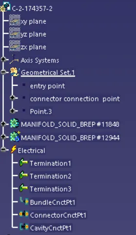
--After that start the Electrical Part Design Workbench in Catia to define the connector electrically.
--First we select the define connector option from the toolbars and then we select the connector body and also assign the
number of terminals to the connector which in this case are 3 terminals.
--Then we select the define bundle connection point option from the toolbars and then we select the connector body,
bundle contact face for representation, mid-point for point, and again bundle contact face for initial condition and then
click on ok.
--Then we select the define connector connection point option from the toolbars and then we select the connector body,
mid-point for representation, contact face for contact, Y-axis for coincidence and X- axis for orientation and then click on
ok.
--Then we select the define cavity connection point option from the toolbars and then we select the connector body,
bottom side mid-point as representation, mating face for contact, Y-axis for coincidence and X- axis for orientation and
then click on ok. This will fully define our connector electrically.
--Save the file.
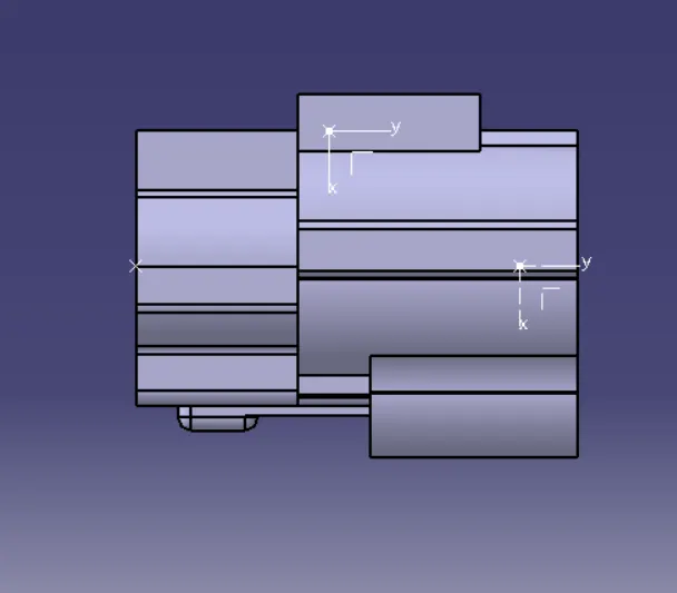
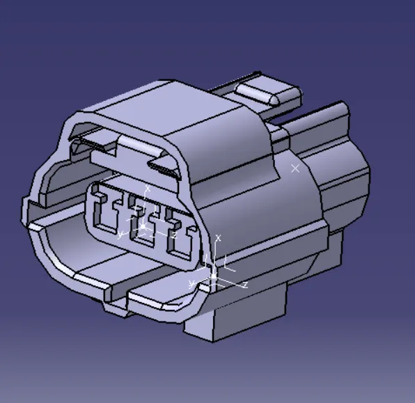
VIEWS OF Tyco 174357-2 & Tyco 85229-1
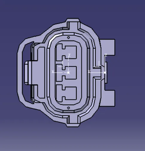
TOP VIEW
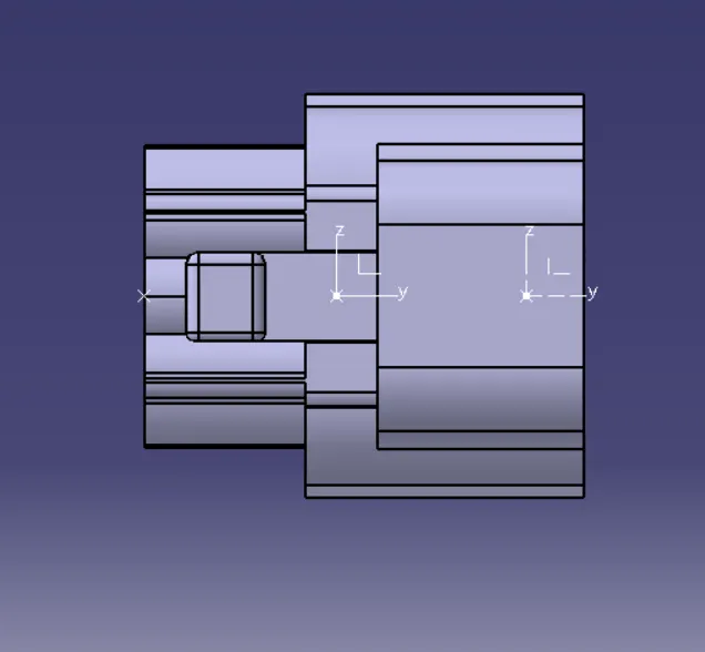
SIDE VIEW
FRONT VIEW
ISOMETRIC VIEW
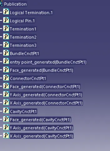
TREE STRUCTURE
MOUNTING CLIP
--First open the 3D CAD data in Catia and then convert the file format(ex: .igs,.stp) to .CATPart.
--Then define the clip geometrically in the Catia Part Design Workbench. To do that we can just create a mid-point and an
axis system with that mid-point as reference on the face which will have contact with the connector. This will allow us to
fully define our clip geometrically.
--After that start the Electrical Part Design Workbench in Catia to define the clip electrically.
--First we select the define mounting equipment option from the toolbars and then we select the clip.
--Then we select the define cavity option from the toolbars and then select the clip body, mid-point for
representation, contact face for contact, Y-axis for coincidence and X- axis for orientation and then click on ok. This will
fully define our connector electrically.
--Save the file.
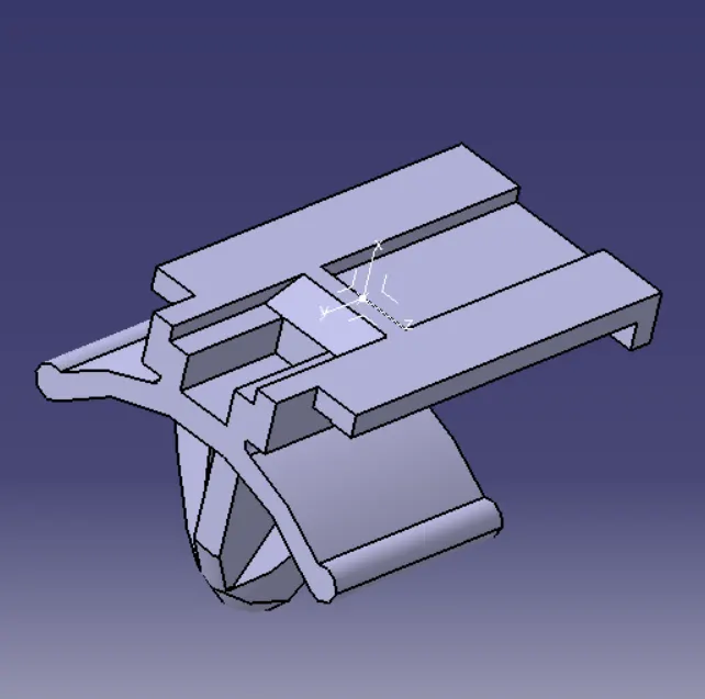
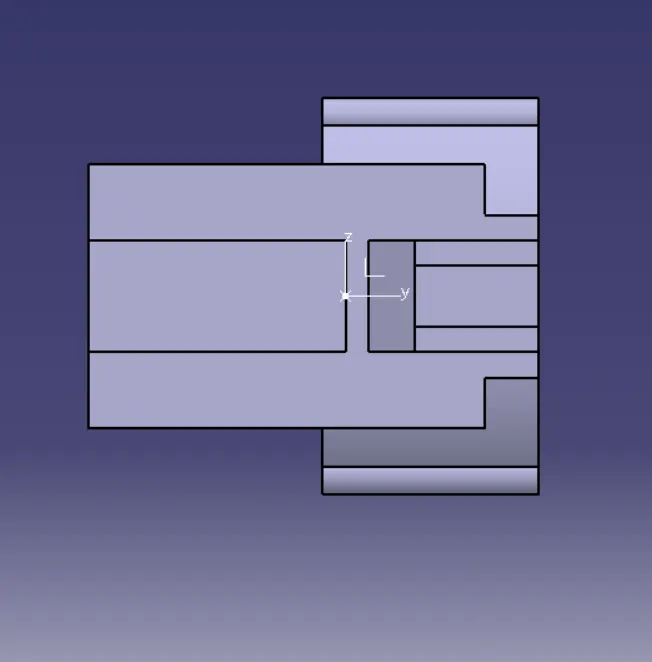
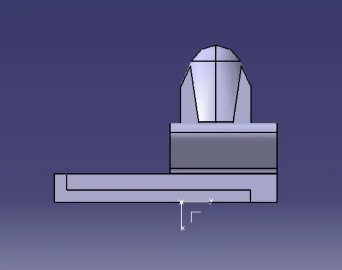
VIEWS OF MOUNTING CLIP
ISOMETRIC VIEW
TOP VIEW
SIDE VIEW
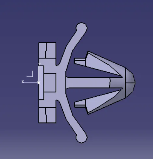
FRONT VIEW
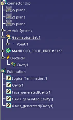
TREE STRUCTURE
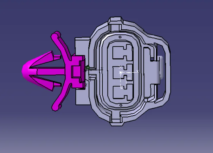
CONNECTOR AND CLIP ASSEMBLY
--Start the Assembly Design Workbench in Catia. Copy the connector and clip parts and paste in the assembly tree.
Rotate both the models in order to give them proper orientation so that they can come in contact properly.
--Start the Electrical Assembly Design Workbench in Catia. Select the connect electrical devices option from the toolbars
and then select the connector and clip to mount then together.
--Save the file.
VIEWS OF ASSEMBLY
ISOMETRIC VIEW
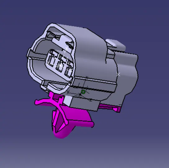
TOP VIEW
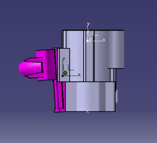
FRONT VIEW
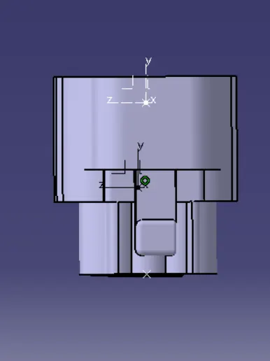
SIDE VIEW
CONCLUSION
Downloading the 3D CAD files form the te.com website and then defining the parts electrically and further creating a
catalogue for the components is done.