Wiring harness design in CATIA V5 - 3D modeling Week 2 Challenge
Aim:
- To define Electrical properties of the given components.
OBJECTIVE:
- Downloading the 3D CAD files form the te.com website and then defining the parts electrically and further creating a catalogue for the components.
- PART - 1: DEUTSCH DT06 - 08SA:
- The First Step is to download the Connector from the website and convert the file into catpart.
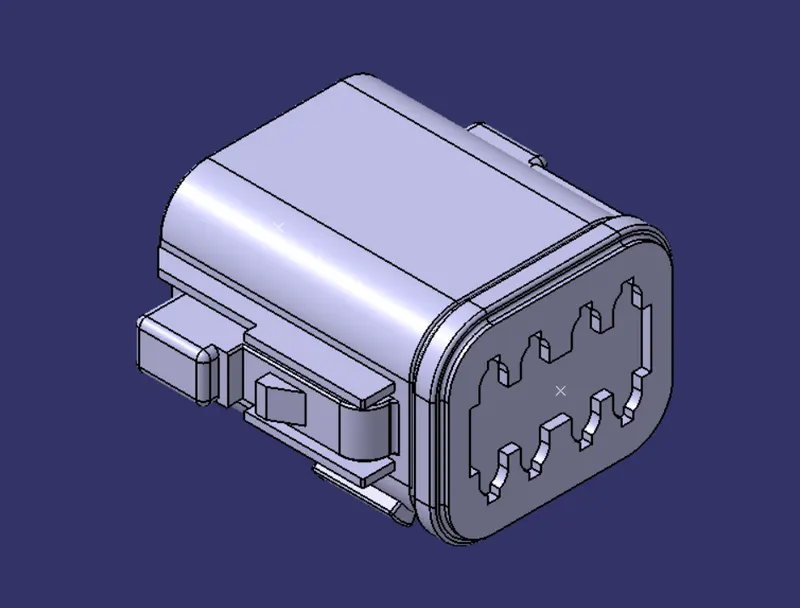
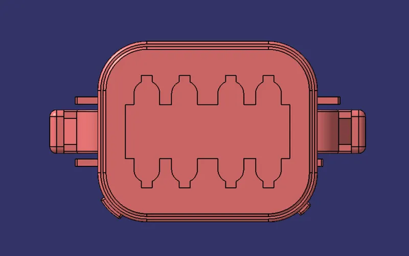
- And the Next Step is to define the connector side and Bundle side .
ConnectorSide:
BundleSide:
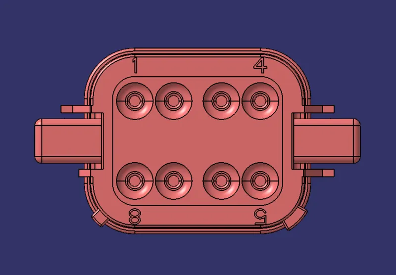
- The Next Step is to create the midpoint in the bundle side to determine bundle connection properties.
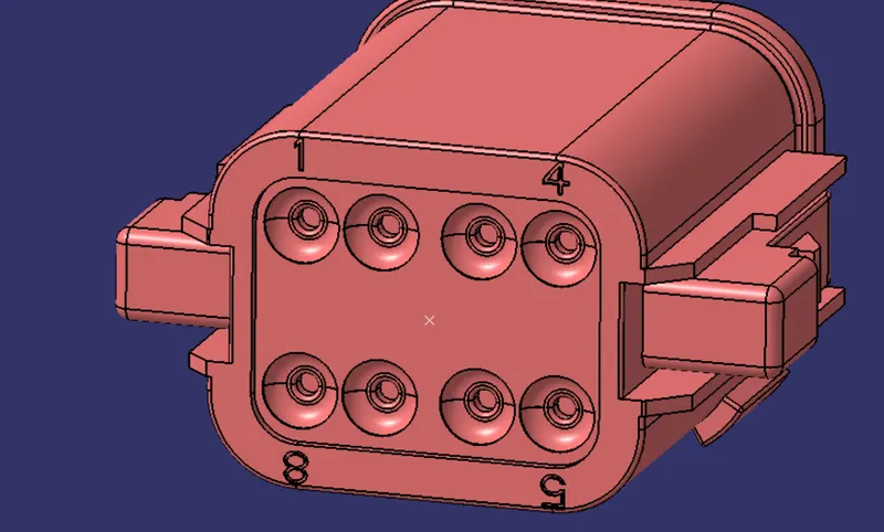
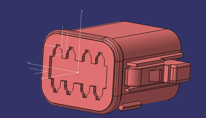
- Same for the connector side mid point is created and axis system is created by taking origin as the created point
- Where,
X- axis - Towards the locking side ,Y- Axis - Normal to the connector face.
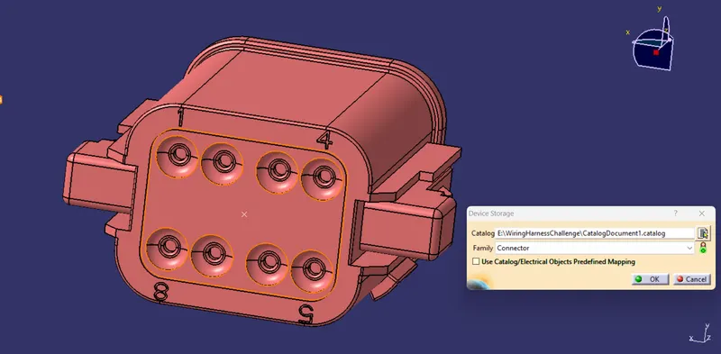
- The next step , go to the Electrical Part Workbench to Define the Connector and terminals and Connector connection point and bundle connection point.
- After Defining the connector and terminals.
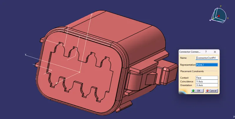
- Then define the connector Connection point
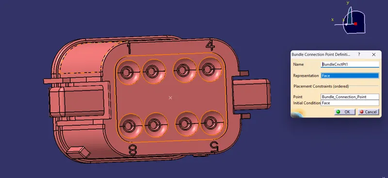
- Then Define the Bundle Connection Point
- Now save the part and add the part to the Catalogue created for the connectors so that it can be used later.
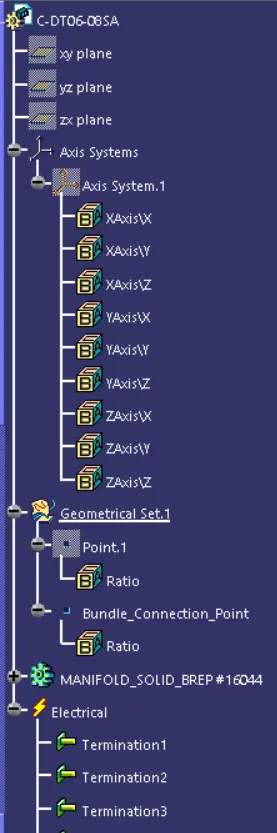
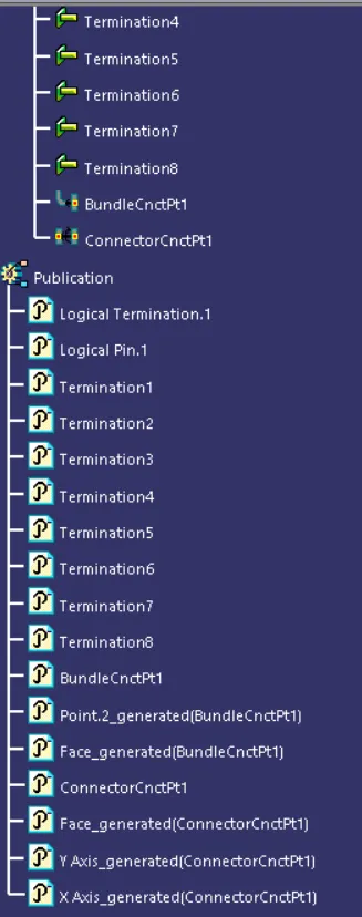
Tree Structure:
- PART - 2: TYCO 174357 - 2:
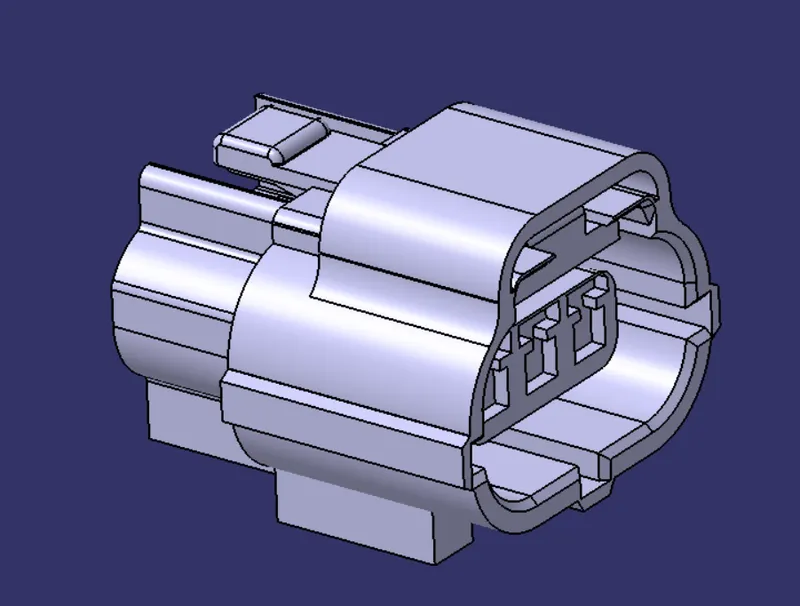
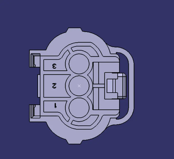
- same as previous determine the bundle side and create midpoint and connector side and create midpoint and axis system.
BundleSide:
ConnectorSide:
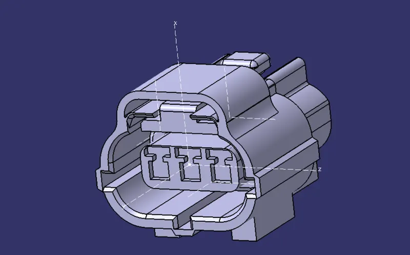
- Create a point for the Mounting clip at the required cavity position and create an axis system through the point for the cavity clip.

Connector Connection Point:
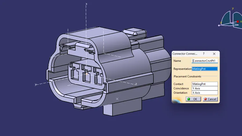
Bundle Connection Point:
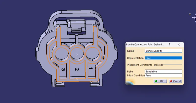
Cavity Connection point:
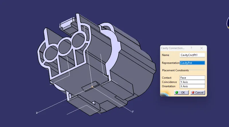
- Now save the part and add the part to the Catalogue created for the connectors so that it can be used later.
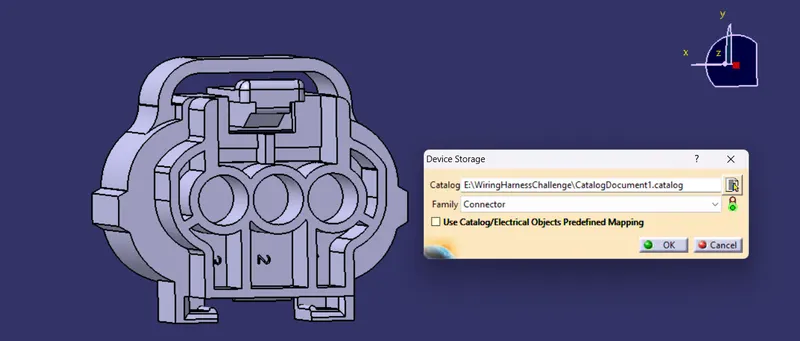
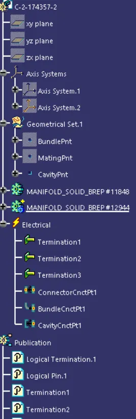
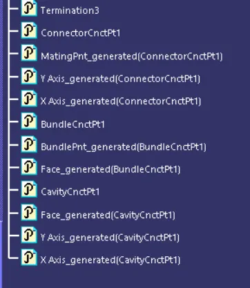
Tree Structure:
- PART - 3: TYCO 85229 - 1:
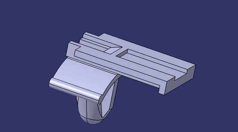
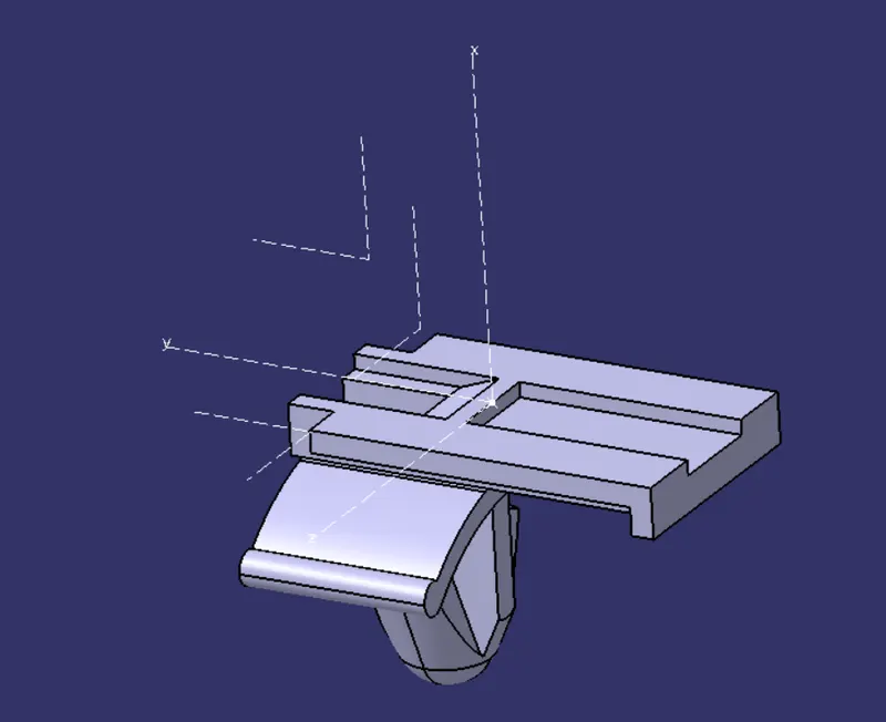
- Create a mid-point at the location where the mounting equipment will be fitted with the connector.
- Create an axis system through the point.
- Define the axis as per the orientation defined in the connector in which the mounting equipment will be assembled.
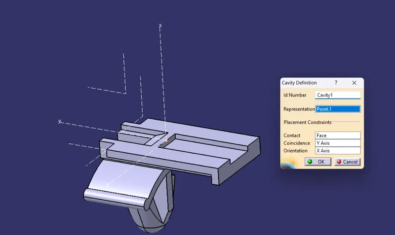
- Go to the Electrical Part Design Workbench to define the electrical properties.
- Define the object as the Mounting equipment.
- Then define the same as cavity.
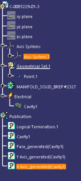
Tree Structure:
Electrical Assembly of part 2 and part 3 :
- Since the connectors and clips are electrically defined , navigate to electrical assembly Design work bench align them and using connect electrical devices select the components.
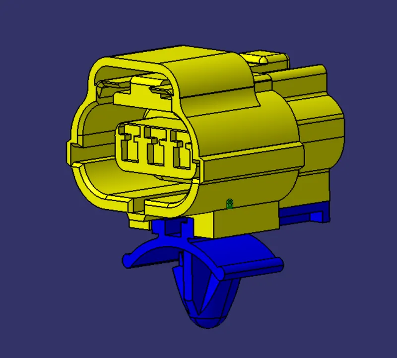
Tree Structure:
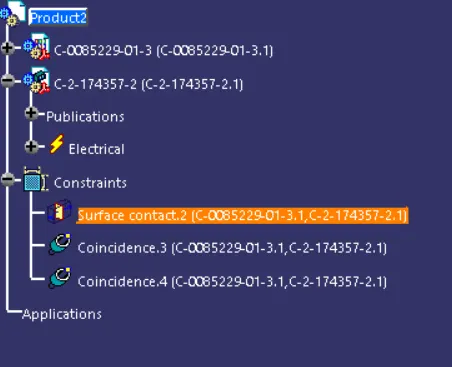
CATALOGUE DOCUMENT:
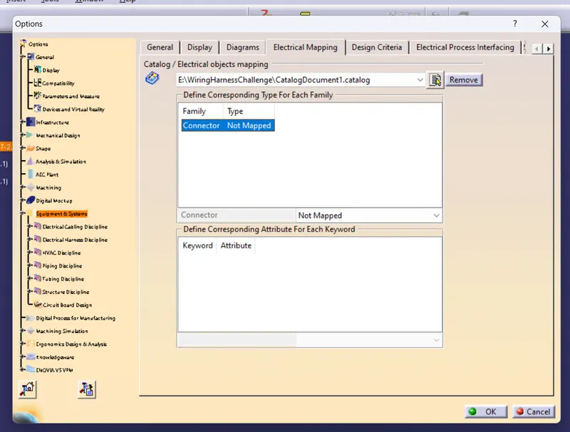
- First a new 'catalogue document' is created and then add family is selected in order to add the group to the catalogue document.
- The name of the family is given as the 'connectors' and the catalogue document is saved in the desired folder.
- After defining the electrical properties, the components are saved in the catalogues so that it can be used in the feature without again defining the electrical properties.