Wiring harness design in CATIA V5 - 3D modeling Week 2 Challenge
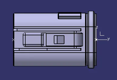
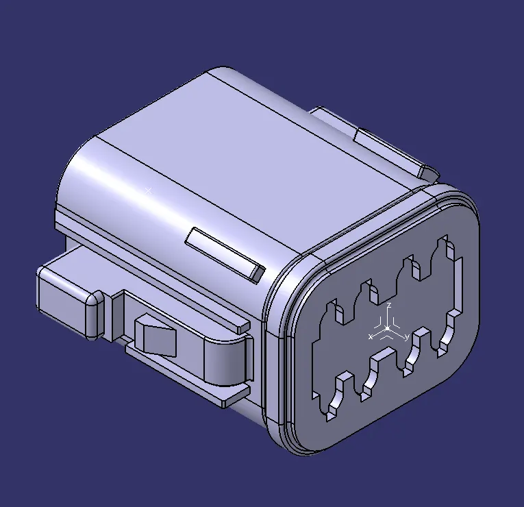
DT06-08SA
Front View
Top View
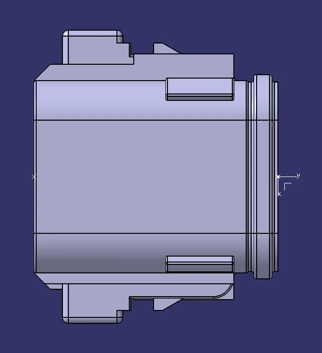
Side View
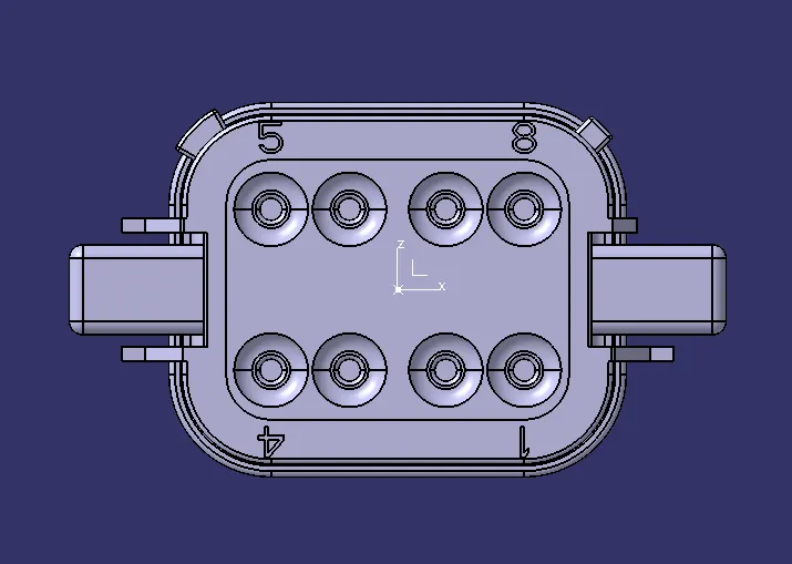
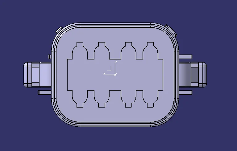
Isometric View
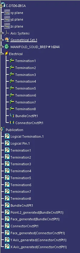
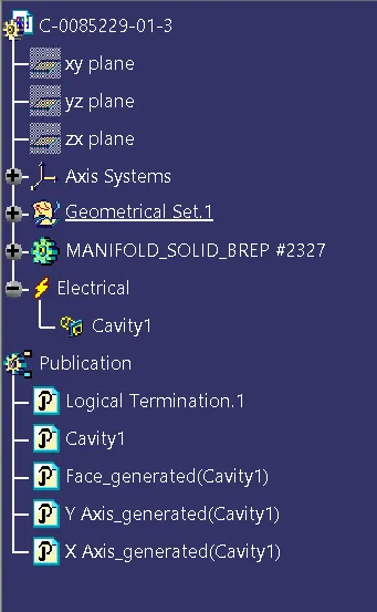
Structure Tree
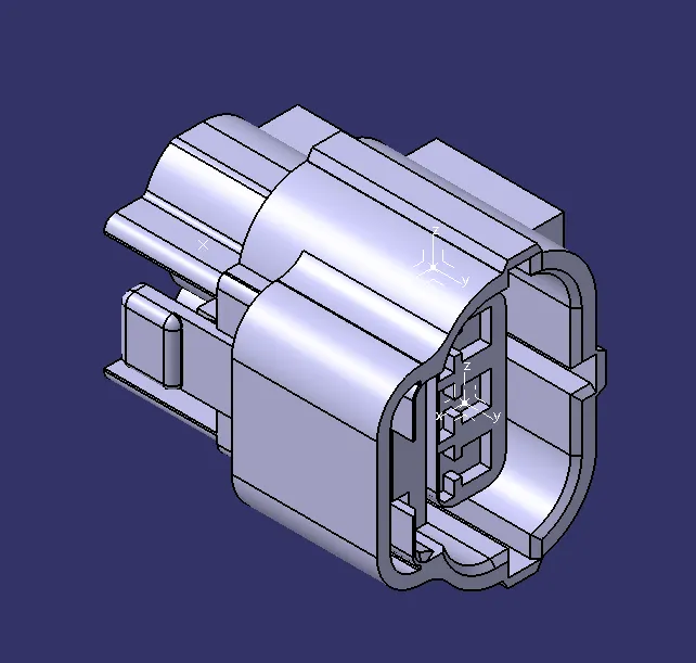
Tyco 174357-2
Front View
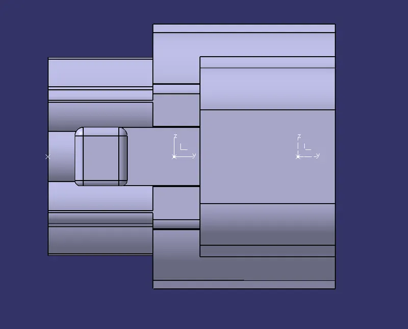
Top VIew
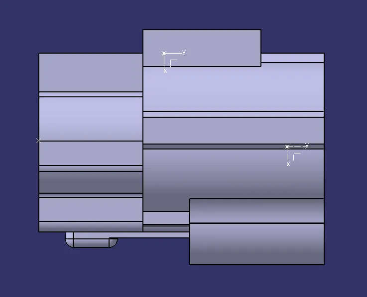
Side Views
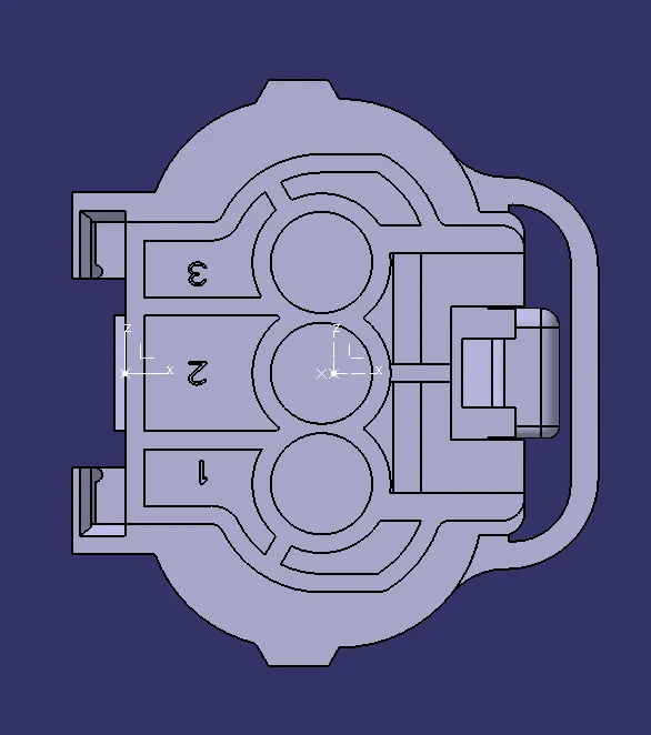
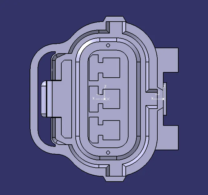
Isometric View
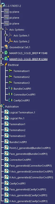
Structure Tree
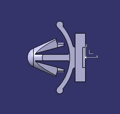
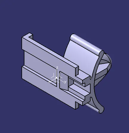
Tyco 85229-1
Front VIew
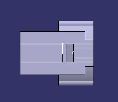
Top View
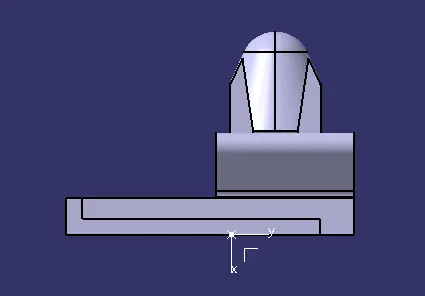
Side View
Isometric View
Structure tree
Electric Connectors Defining and Assembly with Clips
What are Electric connectors?
Electric connectors are electric device which are used to make a electric connection between two terminals. These connectors are made of plastic material as they are good insulator and bad conductor. Electrical connectors can be used to transmit power, signals, or data between two or more devices.
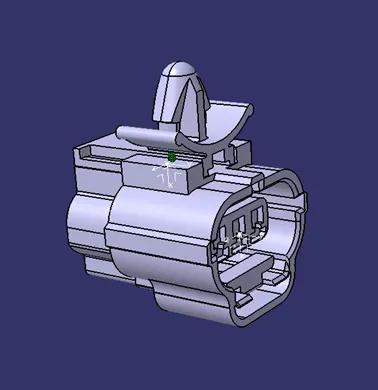
Here shows the image of the connectors.
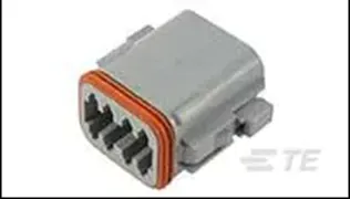
In Catia we will define this connectors into a electrical properties such as define connector, define bundle entry point and define connector connection point.
Electrical Part Design in Catia
In CATIA, electrical part design refers to the process of creating 3D models of electrical components, such as connectors, wires, cables, and harnesses, using specialized tools and features within the software. The electrical part design process in CATIA is a specialized process that requires a deep understanding of electrical engineering principles, as well as expertise in using CATIA's electrical design tools and features.
Defining connector in Catia:
We can download the connector from the websites like TE.Connectors, Deutsche Connector, Molex, APTIV etc., from where we can download connector CAD file and then we can define in Catia.
First we will open connector CAD file in Catia so that we can define the connectors as electrical component.
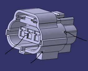
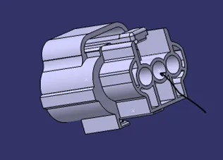
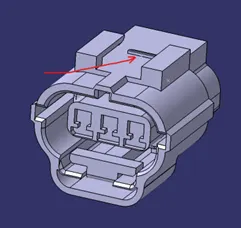
We have to put the point on this location so that we can define connector as an electrical component. We also put the axis system to this point so that we can define the connector-connector point and connector-cavity point. For the clip mounting we have to define extra mounting point.
The axis should be placed exactly same orientation of axis as on the connector and mounting clip. Normally,
- Y-Axis: - Should face in the direction of connector
- X-Axis: - Should face toward the locking of the connector
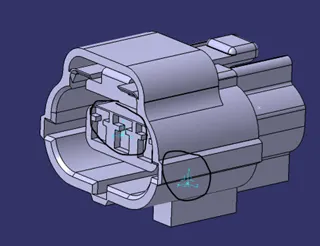
Note: - It is not necessary to put in the same direction, what necessary is should be identical to the connector and clip for proper connection.
To add electrical properties to the connector: -
- To add the electrical properties first we have to select the command ‘define connector’ which look like the below mentioned image

- Click on the connector and it will open a dialog box where number of terminal should be given (we can see on the back of the connector how many terminal we have or else we can see in the product detail which is available on the website from where we downloaded)
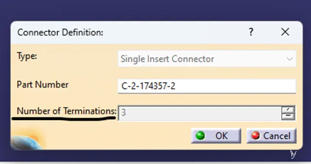
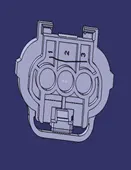
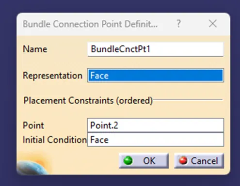
Define Bundle Connection Point
- After that select the command ‘Define Bundle connection Point’ to give the wire or Bundel entry to the Connector. It look like given below

- Select the connector
- It will open a dialog box where we have to define different parameters
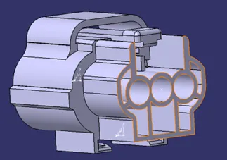
- ‘Representation’ where we will select the face of the entry point
- ‘Point’ where we will give point that we had made for the bundle entry
- ‘Initial Condition’ this should be perpendicular to the bundle entry, normally we select the same face
Define Connector-Connector Point

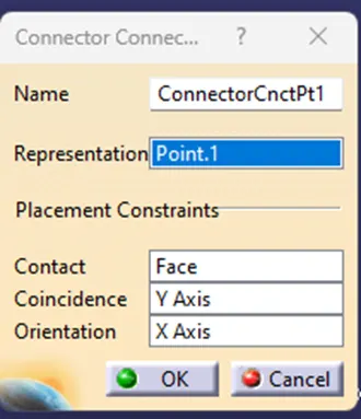
- Select the Connector
- It will open the dialog box where we can define different parameters
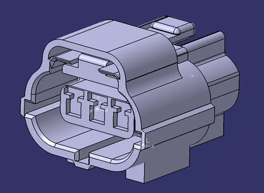
- ‘Representation’ select point that we created for the connector-connector point
- ‘Contact’ – Select Face on which we created the face (it is important to select correct face because this will be contact reference surface for connection)
- ‘Coincidence’ - Select the axis which is perpendicular to the contact face which is Y-Axis in our case
- ‘Orientation’ – Select the axis facing toward the lock direction which is X-Axis in our case
Define Cavity Connection Point
- If connector is need to be mounted on clip this command is necessary

- Select the connector
- It will open the dialog box where we have to define different parameter
- ‘Representation’ – Select the point that is created for the cavity connection
- ‘Contact’ – Select the face which will be in contact in with mounting clip face
- ‘Coincidence’ – Select the Y-Axis just like the Connector-Connector Point
- ‘Orientation’ – Select the X-Axis which toward the lock direction (Make sure that the axis orientation of the clip and cavity is similar for the proper connection)
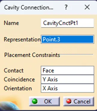
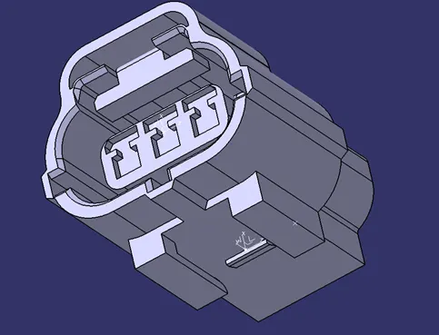
This is how the Connector is defined as the electrical component in the Catia for the Electric Harness.
Define Mounting Clip
To define a mounting clip we need to define a point and also the axis system which is similar to the connector, in simple way when we make an assembly we have to make sure that it will fit correctly. We can download clip from the same website.
Define Mounting Clip: -
Before defining the mounting clip we have to create the point of the contact that should coincide with the connector and also create axis system on that same point with same orientation of the Axis Direction, because in assembly it will make axis to axis connection.
- Select the command ‘Define Mounting Equipment’

- Select the mounting clip and it will open a dialog box where we can define different parameters
- ‘Representation’ – Select the point that is created on the contact surface of the mounting clip
- ‘Contact’ – Select the face that is going to be in contact with the connector
- ‘Coincidence’ - Select the same axis that is selected on the connector
- ‘Orientation’- Select the same axis that is on the connector
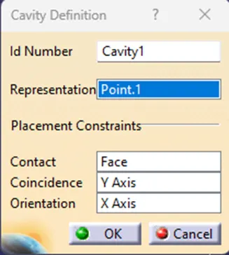
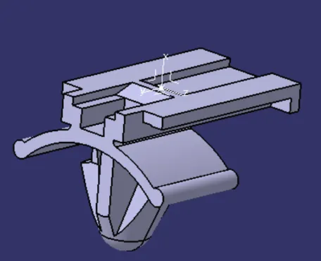
Electrical component and publication of the component: -
When we define electrical component, it will be shown under Electrical Definition. It will also do publication of all the terminal and the definition of connection. All this will be showed in the structure tree.
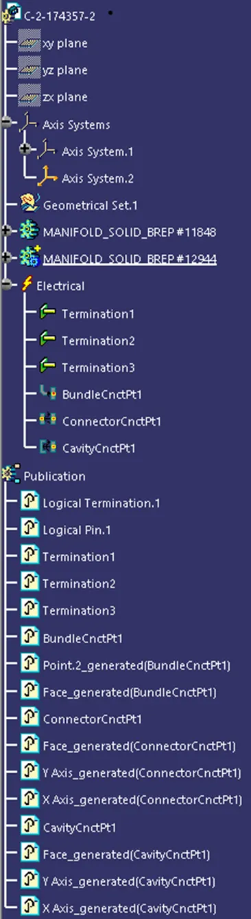
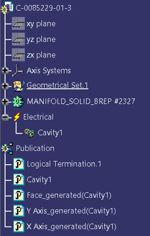
Assembly of the Connector and Mounting Clip
Assembly is done in the Electrical Assemby Design. We have to open connector and mounting cliop in assambly design and the create the electrical connection between the connector and connector, also for mounting clip we create the electrical connection. We use command ‘Connect Electrical Device’ for creating the electrial connection between two electrcial component.
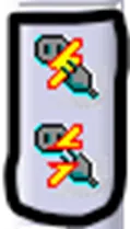
This are the two command we use for electrical connection. Top is for connection and bottem breaking the connection.
To create the assembly, better make the proper orientation on both the device for the better connection. Also try to put in such a way that it is easy to assembly.
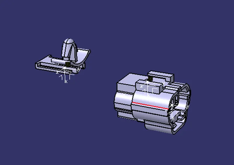
- Select the Connect Electrical Device
- Select the both device
- It will autometically prompt the fissible available connection
- Select the proper axis if there are more then one mounting clip or connector are available
Conclusion: -
This is the breif discription of the defining the Connector Electrical Properties and also how to assemble the mounting clip.