Wiring harness design in CATIA V5 - 3D modeling Week 2 Challenge
Wiring harness design in CATIA V5 - 3D modeling Week 2 Challenge
AIM:
Download following connectors & Connector clip cad data from given link & define it as Electrical Connector using Electrical Part design Workbench. Define all the necessary properties to Connectors & Clip.
SOLUTION :
- All the links are clicked which redirects us to te.com
- We have downloaded all the igs zip files
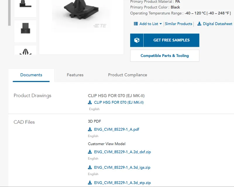
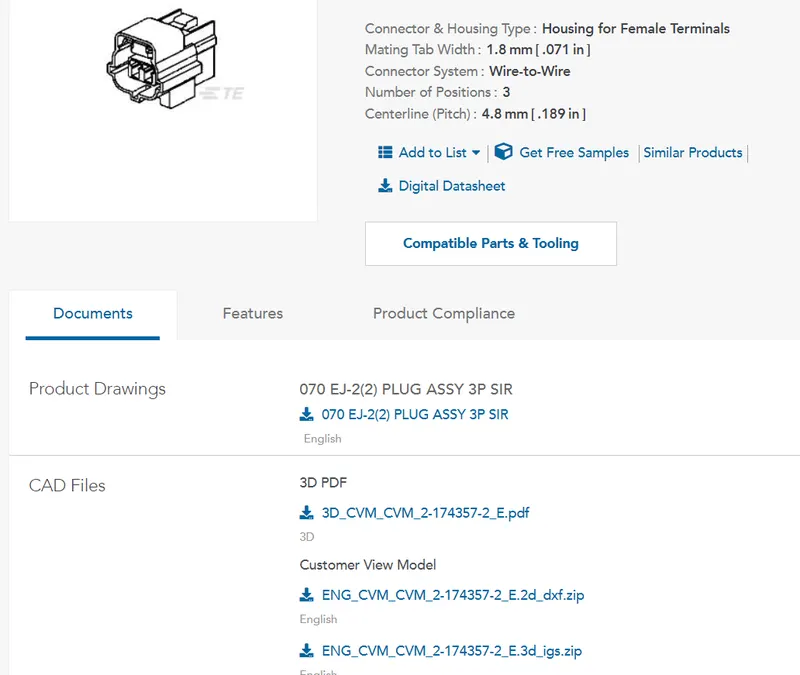
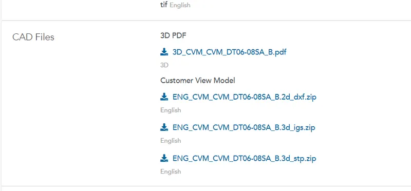
- The zip files are extracted
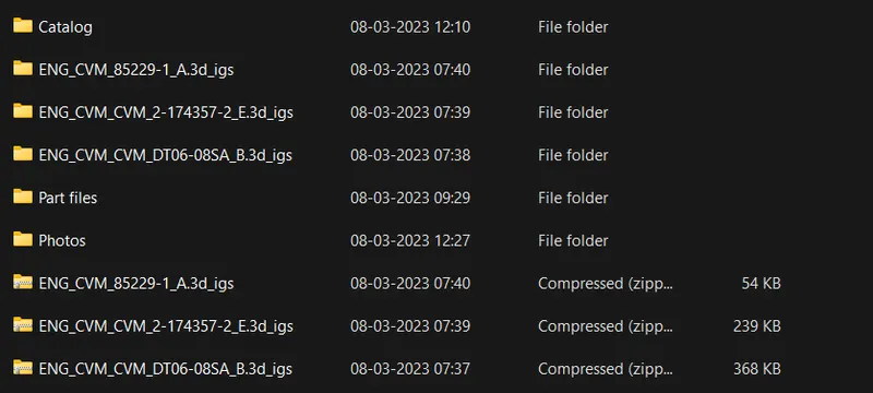
- Files are opened in CATIA and converted into Part files

- Connectors and clip is opened in the CATIA in part design.
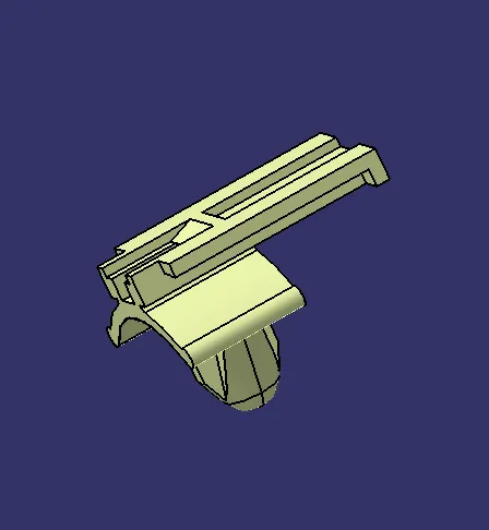
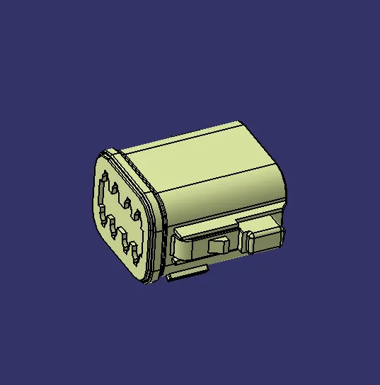
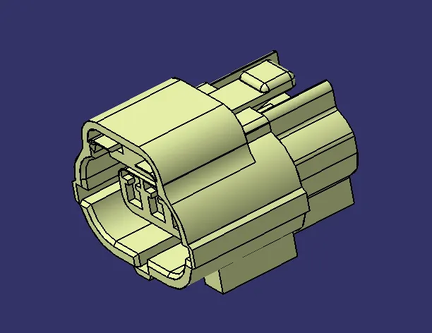
- Points and axis are created to define electrical properties of the connectors and clip.
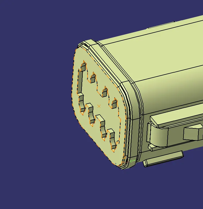
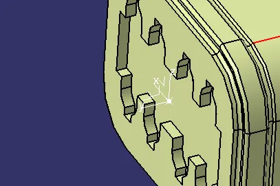
Connector : C-DT06-08SA
- Bundle entry point is created at the wire side of the connector. it is drawn at the center of the joining edge.
- Mating point is created so that we can create connector cavity axis, This is also created at the centre of the face.
- Connector cavity axis created at the point created. with Y axis facing away from the connector and X at the locking side and the Z the other side.
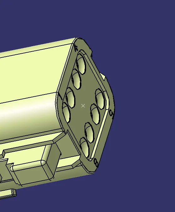
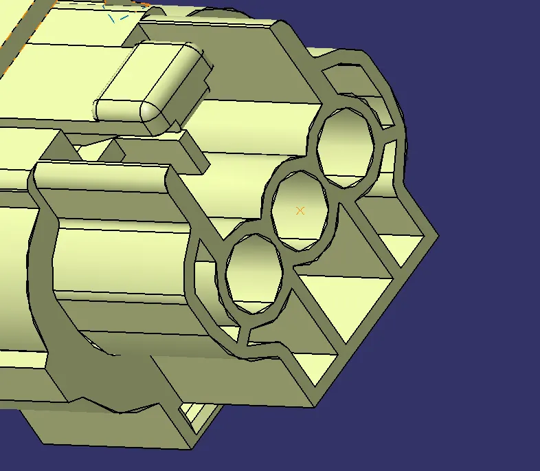
Connector : C2-174357-2
- Bundle entry point is created at the wire side of the connector. it is drawn at the center of the joining edge.
- Mating point is created so that we can create connector cavity axis, This is also created at the centre of the face.
- Connector cavity axis created at the point created. with Y axis facing away from the connector and Z at the locking side and the X the other side.
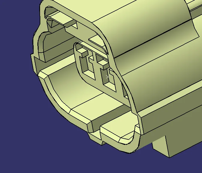
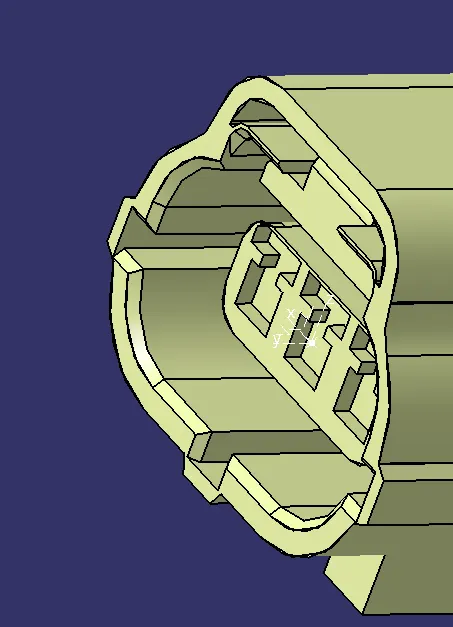
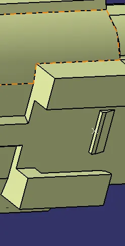
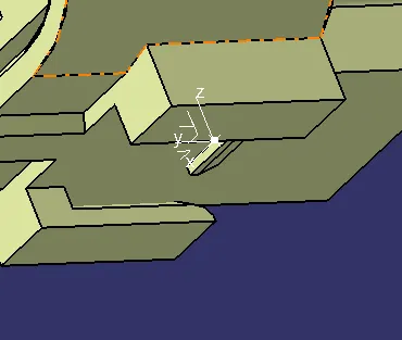
- Along with this provision to clip is also given.
- Apoint is created at the locking area of the mounting clip
- Axis is created at the point created. with Y axis facing away from the connector, Z and X other side.
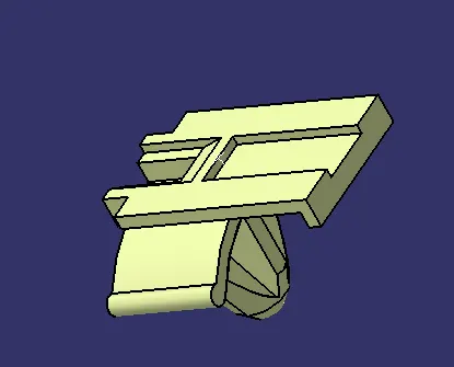
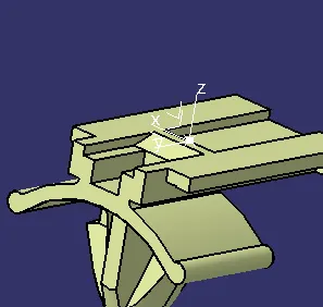
Clip : C-0085229-01-3
- Point is created on the joining face of the clip
- Axis is created at the point created. with Y axis facing away from the clip, Z and X other side. Refer the connector and align accordingly
Electrical part design :
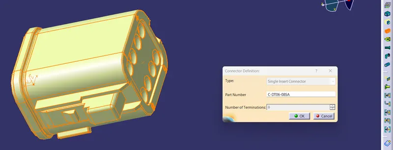
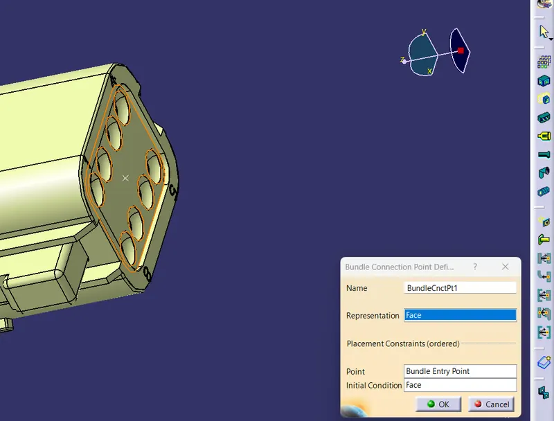
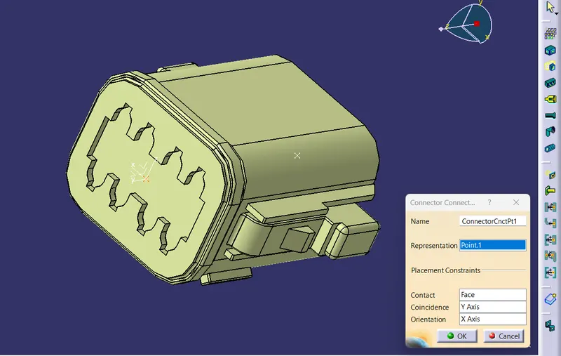
Connector : C-DT06-08SA
- Part is defined as connector
- Bundle connection point is defined using the command.
- Connection connector is also defined
- Refer photo for the selections
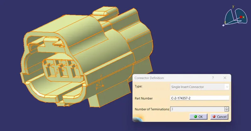
Connector : C2-174357-2
- Part is defined as connector
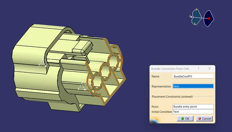
- Bundle connection point is defined using the command.
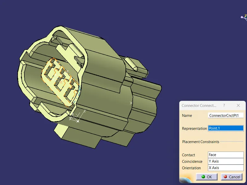
- Connection connector is also defined
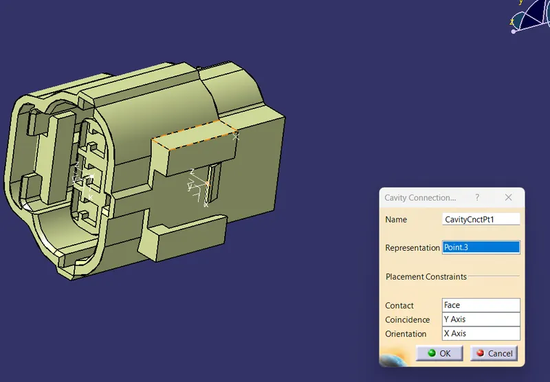
- Cavity connector is also defined to join with the clip
- Refer photo for the selections
Clip : C-0085229-01-3
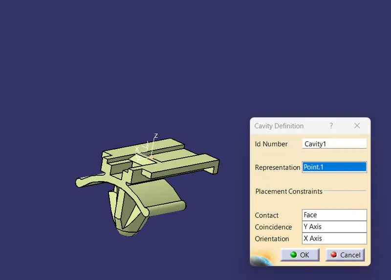
- The Mounting clip is defined as the cavity
- So we can join with the above connector
- Refer photo for the selections
- axis selection are given similiar to connectors
Electrical Assembly Design:
- Copy and Paste the parts for assembly
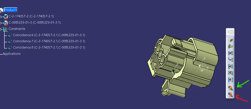
- Click the connect electrical devices and click the clip and connector, It will constraint accordingly
- If you click disconnect electrical device and click the clip and connector, it will disconnect.
- Green arrow - connect electrical device
- Red arrow - disconnect electrical device
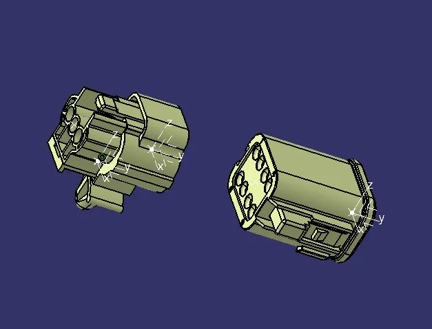
- Here we cannot connect the other connector because the terminations are different
RESULT :
Hence we have downloaded the following connectors & Connector clip cad data from given link & defined it as Electrical Connector using Electrical Part design Workbench and Defined all the necessary properties to Connectors & Clip.