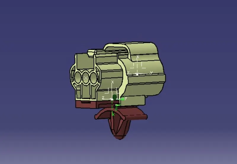
Wiring harness design in CATIA V5 - 3D modeling Week 2 Challenge
STEPS TAKEN TO IMPLEMENT FOLLOWING DESIGNS:
- Downloaded following connectors & Connector clip cad data from given link.
- following parts defined as electrical connector.
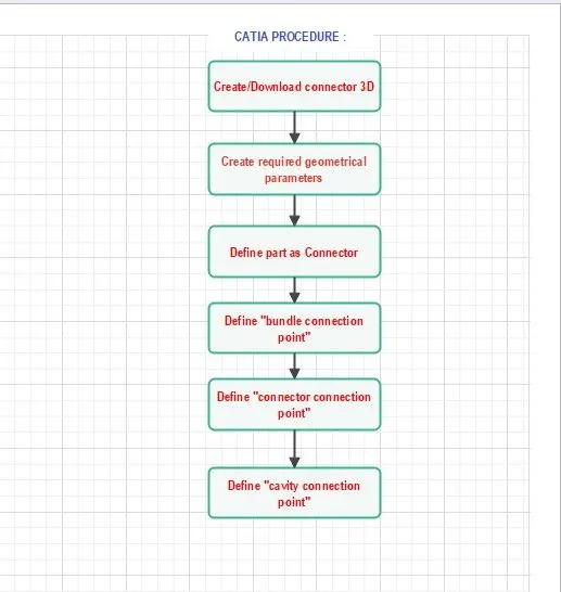
- we have followed the following procedure to make assembly design.
REQUIRED PARAMETERS:
Geometry parameters:
- Points & Co-ordinate system(axis)
Connector connection point:
- this point is used for the connection of one connector to another connector.
Bundle connection point:
- this point defines where the harness bundle segment point will end when routed to the electrical connector.
Cavity connection point:
- this point is used to define the connection of connector to a connector clip.
- this parameter in catia only applied to the connector clip.
CONNECTOR NUMBERING SYSTEM:
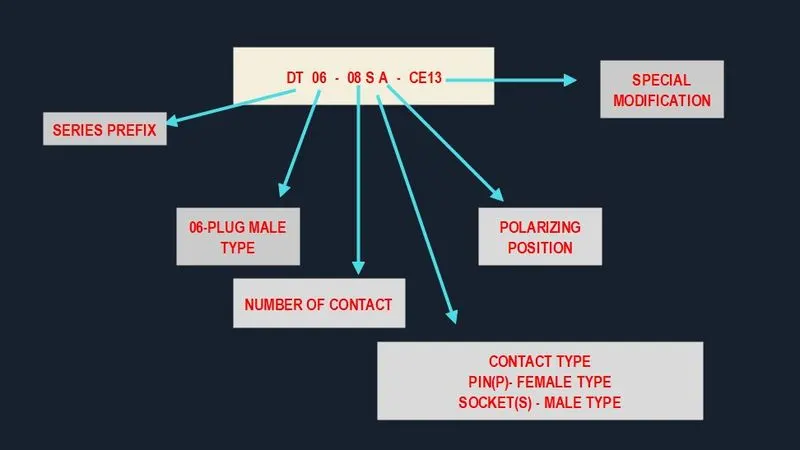
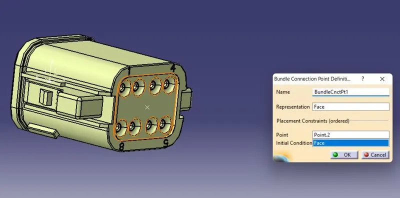
1. Deutsch DT06 – 08SA
- Connector connection point
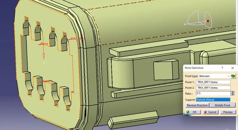
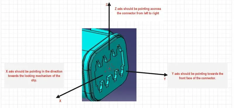
- Bundle connection point
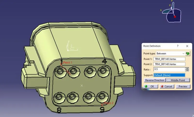
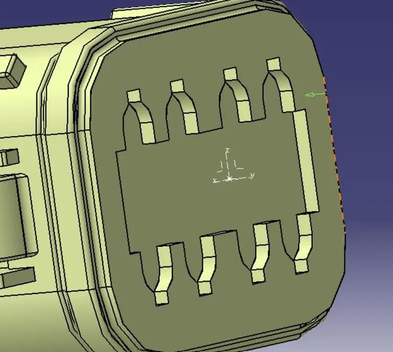
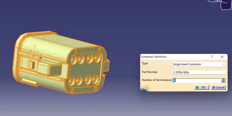
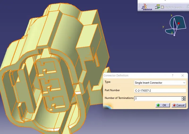
- switched to 'Electric part design' define the part as connector in CATIA.
- in following fig. we have given number of termination as 8 because there are 8 entry points for wire.
- Bundle connection point
2.Tyco 174357-2
STEPS TAKEN:
1.found midpoint.
2.created connector connection point.
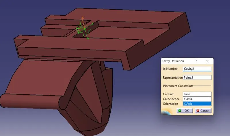
- contact - Face
- coincide - Y axis
- orientation - X axis
3.created connector connection axis system.
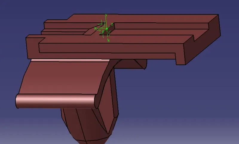
4.created cavity connection point.
5.created cavity connection axis point.
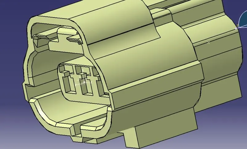
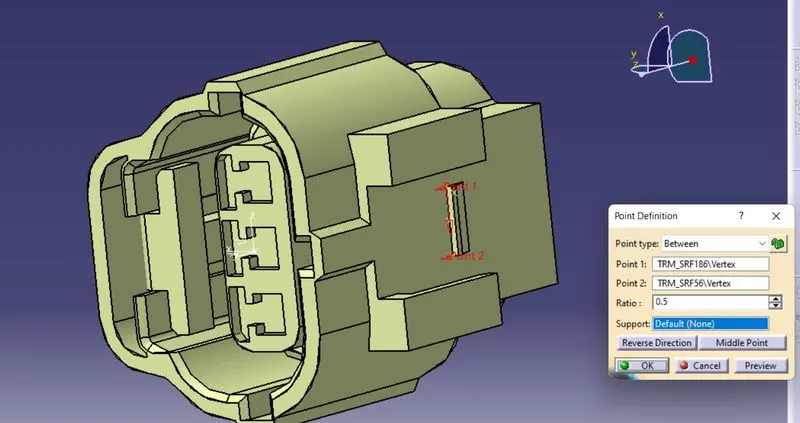
6. switched to electric part design and defined part as connector
3. Tyco 85229-1
STEPS TAKEN:
- created midpoint
- created cavity connection point
- created cavity connection axis system similar as we created for connector 2.
- switched to electric part design and defined part as cavity part.
- created cavity connection point
ELECTRICAL ASSEMBLY DESIGN:
STEPS TAKEN:
- we have imported 2, connector and 3. cavity in electrical assembly design window.
- meshed two parts with the help of connect two parts command.
- parts meshed with each other by selection of matching axis system of two parts.
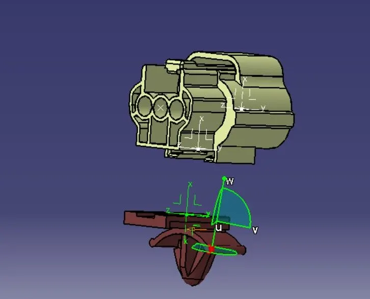
- FINAL ASSEMBLY DESIGN