Wiring harness design in CATIA V5 - 3D modeling Week 2 Challenge
DESIGNATION FOR ELECTRICAL CONNECTORS AND CLIPS
Steps to be followed in downloading and assigning connector to module
- Go to File>New>Catalog Document
- Click on Add Family icon
- This allows the user to add the type of Catalog to be created for intended use
- In this case, A new Family is created in the name of Connectors
- Standard type is selected from the drop down list and and suitable name is given
- A new catalog for connectors is added
- Save and exit
Steps for downloading and assigning Connectors
- The required Connector and connector clips are downloaded from Tyco site
- Most available type of cad file is .igs, .stp and .dxf
- The required file is downloaded and opened in CATIA V5
- The file is saved as a .cat part and opened in an Electrical part design workbench
- We need to store the saved connector part in the catalog created under the name of connectors
- The Store Device button is clicked and the connector is clicked and the necessary catalog is selected
- Now the Connector is the required catalog and can be accessed anytime
Assigning Connection points to connector
- First, the Connector connection point and Bundle connection points are identified
- The face where the wires enter is where the Bundle connection point should be placed
- A point is created on the face of the terminals in Mechanical Part Design
- Now, Workbench is switced to Electrical Part Design and the Define Equipment is given and the connector is slected
- This feature allows the system to identify the given part as an conenctor
- Now, the define Bundle Connection point is given
- A appropriate name is given and the face of the entry point is given for Representation
- The point created earlier is slected for the point option
- And again the face is selected for the Initial Condition
- This defines the point as Bundle connection point
- The same stpe is repeated for Connector connection point but instead of Bundle connection point, Connector Connection point is selected
- This opens the Connector Connection Point box
- The point created on the other side is selected for point
- The entry face is selected for contact
- The Y axis is selected for Coincidence and the X axis is selected for Orientation
- This creates a Connector connection point
- The same step is repeated if there is a Cavity Connection for the connector Clip
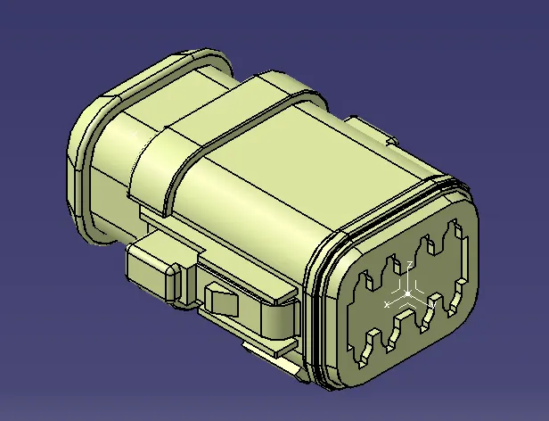
DEUTSCH DT06-08SA
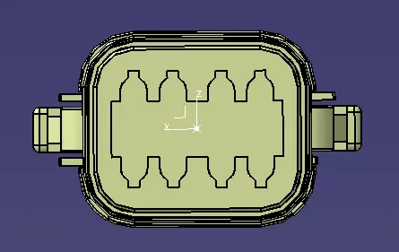
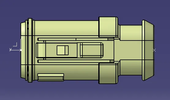
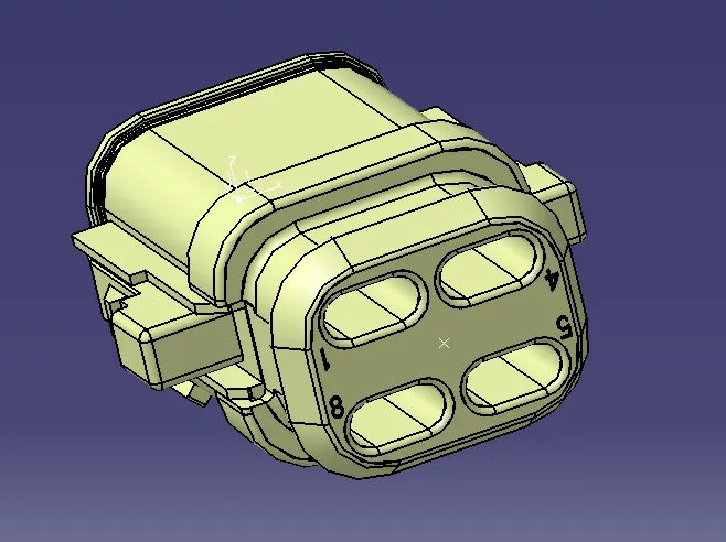
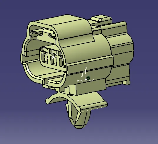
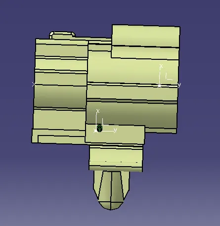
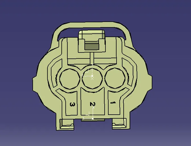
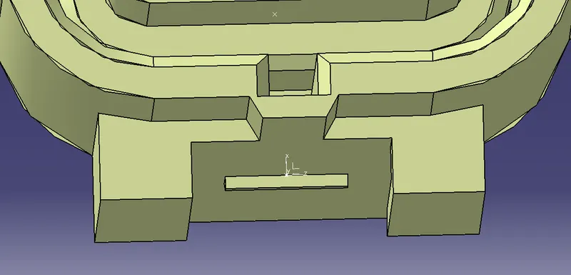
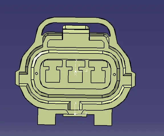
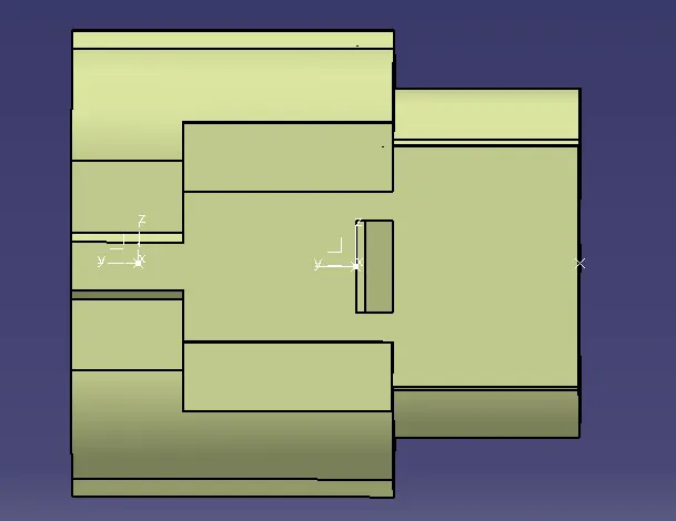
TYCO 174357-2 CONNECTOR
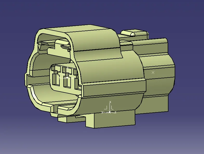
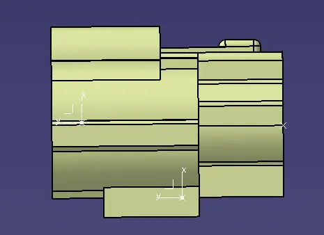
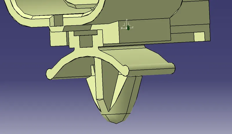
TYCO 85229-1 CONNECTOR CLIP
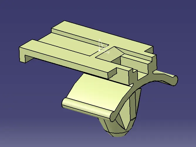
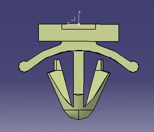
ASSEMBLY