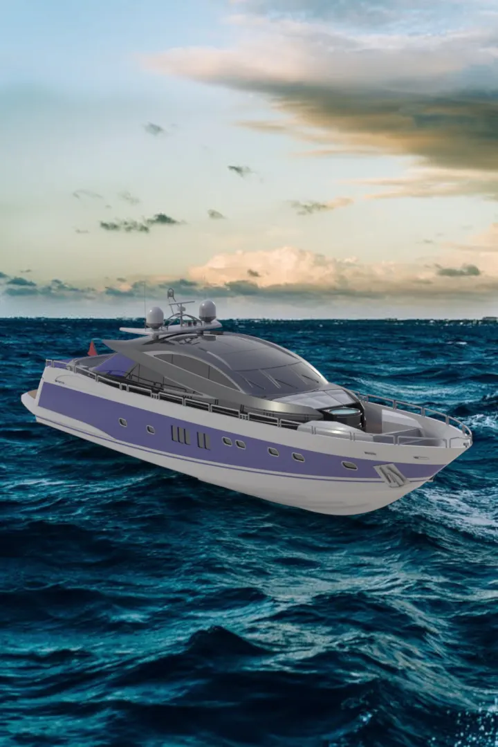
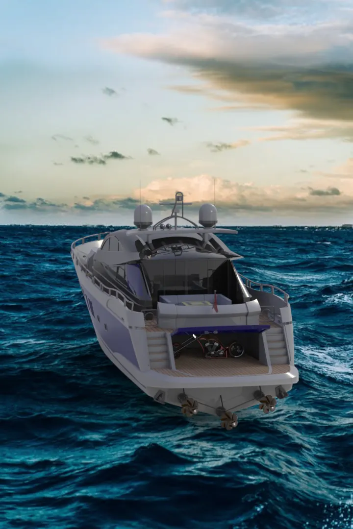
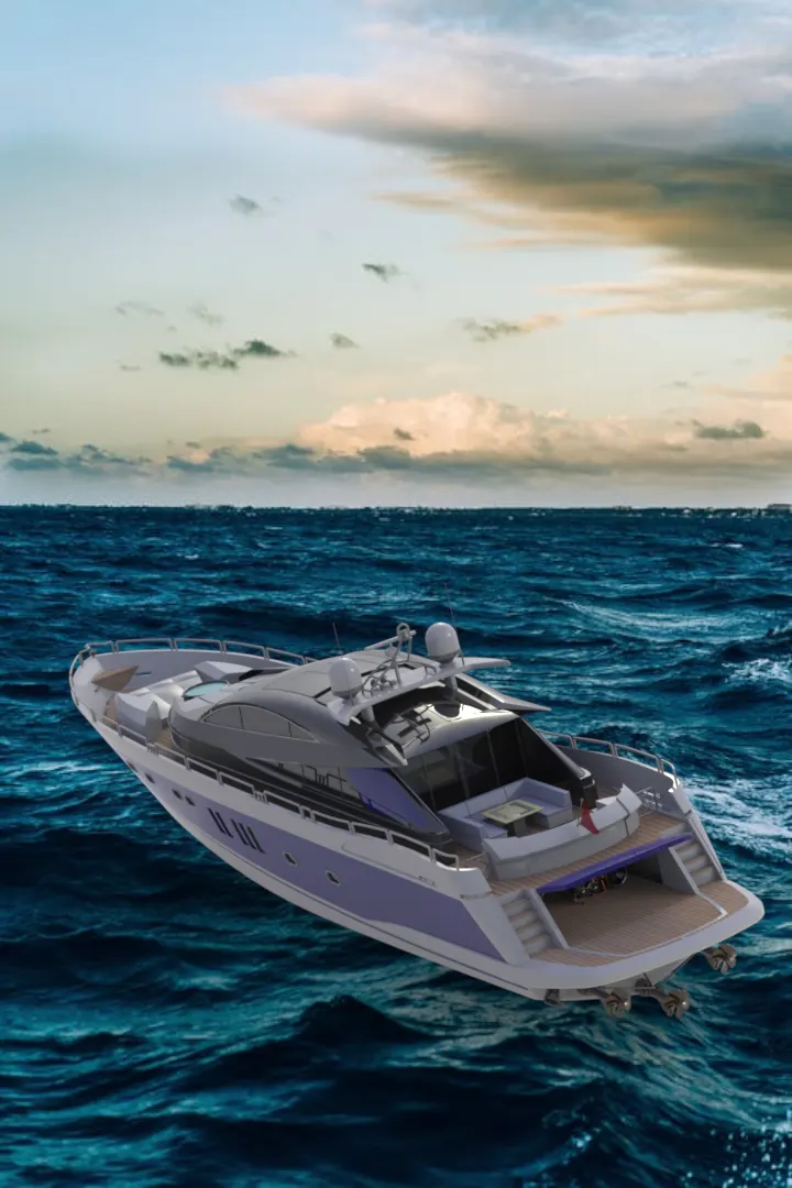
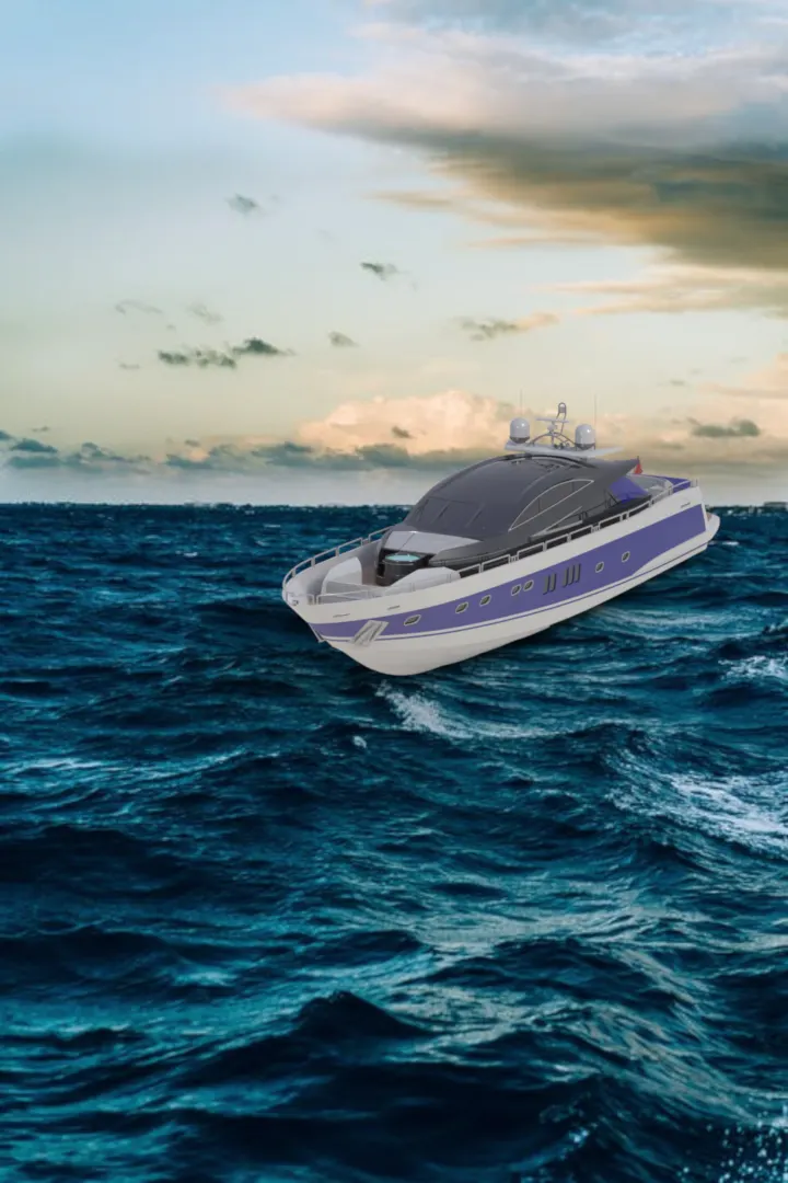
Radar Mast & Final Assembly of Yacht
YACHT MODELLING AND RENDERING USING SOLIDWORKS
INTRODUCTION
This report is to show the things I’ve learnt over the past 4 weeks in Solidworks Surface modeling and rendering of a Yacht. I will be explaining the steps and various tools used in creating the surface and solid model.
OBJECTIVE
- To learn more about the CAD software Solidworks
- To equip myself with the necessary knowledge in solid and surface designing
- To model and assemble the given project (yacht) using various tools in Solidworks
- To render the complete model with its appropriate environment using Solidworks Visualize.
DESIGN APPROACH
The model was divided into sperate solid bodies and later assembled. The parts designed are as follows:
- Propeller
- Radar
- Blueprint Setup
- Hull
- Garage Door
- Front Seat
- Middle Seat
- Rear Seat
- Superstructure
- Radar Mast
- Assembly of Yacht
- Rendering
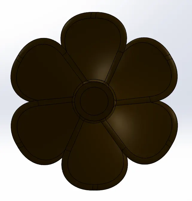
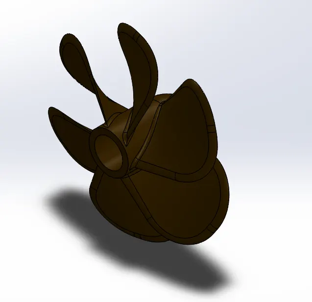
1. PROPELLER
In the process of designing the Propeller, I came across the basic tools that require to sketch and model a part in Solidworks. The basics like commands that were in use for all the parts are:
- Sketching
The basic sketching was done using Solidworks to give the 2D appearance of the propeller. Tools used were line, 3-point arc and fillet.
- Revolved Boss/Base
The revolve option was used to give the model a 3D appearance and the actual shape of the base of the propeller. The cross section was sketched in2d and revolved around an axis.
- Lofted Boss/Base
The loft option was used to create the blade of the propeller and 2 different sketches were used to complete this process.
Once the Revolve and Loft was complete, the Propeller was given fillet to the edges to give it a round finish.
An appearance of RGB 71,45,0 was given to the transmission belt to make it look realistic during rendering.
2. RADAR
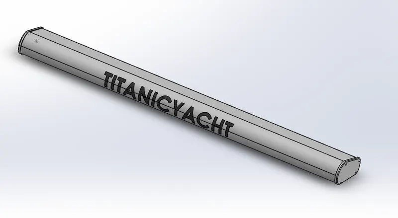
The commands used to create kick stand are:
- Sketch
The basic outline of Kick stand was drawn in a plane in 2D.
- Extrude Boss/Base
This feature allowed us to create an extrude of the 2d sketch. This helped in creating the main structure of the Radar
- Polygon
This feature in sketch allowed to create a polygon in 2d sketch.
- Extruded Cut
This feature was used to create a text cut on the radar without disturbing the main structure.
- Extruded Boss/Base
- Mirror
The mirror option is used to mirror the whole body using a particular plane, thus the model created must be symmetric and fillet should be given at appropriate faces and edges.
The Kick stand had been given an appearance of white and the text an appearance of RGB 70,70,70.

3. BLUEPRINT SETUP
The additional features used to create this part were:
- Sketch Picture
This feature allowed us to make blueprint setup with blueprint images of the ship with various views to create sketches with reference. This blueprint setup was used for the remaining designs. The blueprint setup was saved in different file name before starting a new part and used as a skeleton for the Surface design.
4. HULL
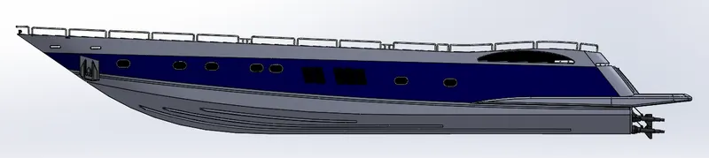
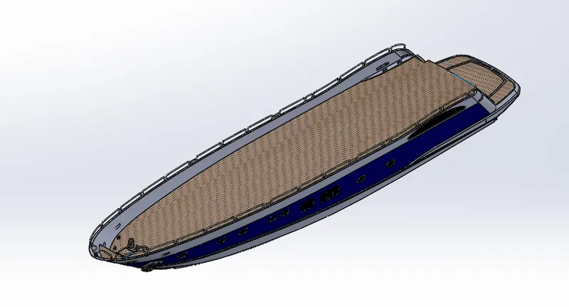
The Hull is the first component of the Yacht design with major Surface design. The features used to create the Hull are:
- Lofted Surface
This feature is used to create a loft between 2 curves or 2 sketches to give a lofted surface. It’s also used to fill the surface gaps with the needed curve of the surface.
- Swept Surface
Swept surface is created by planes, sweep path and guide curves. The swept surface helps cover various surfaces with help of guide curves.
- Extruded Surface
This feature allows us to extrude a given surface from an open boundary surface.
- Extend Surface
This feature helps us in extending the surfaces that have already been created. This is helpful in when converting surface to solids.
- Ruled Surface
The Ruled Surface command creates surfaces that extend out in a specified direction from selected edges. It gives the user a detailed view on how the surface will look like.
- Filled Surface
The filled surface command helps in filling the gaps created when forming a desired surface. This is useful to fill the gaps when surface is open.
- Trim surface
The trim surface is used to trim the unwanted surfaces that are created while creating a surface model.
- Knit Surface
This feature allows us to create a single body when designing. If 2 or more surfaces need to be closed and made into a solid, the knit feature allows us to close it and become a single surface body. It allows to merge the surface bodies into one.
5. GARAGE DOOR
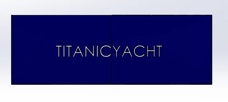
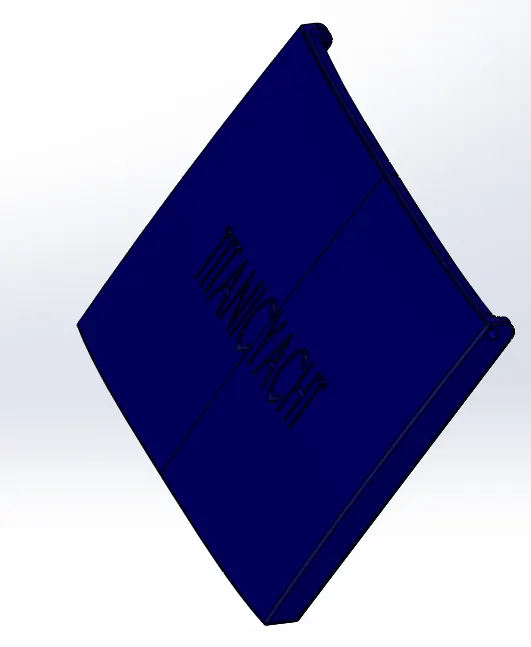
The garage door is a solid model. This model is mirrored, so only one half is modelled. The features used are:
- Extrude Boss/Base
The Extrude feature is used to create the main body of garage door.
- Extrude Cut
The garage door is made into the desired shape using extrude cut from the extruded body.
- Mirror
This feature allowed us to mirror the garage door on the other side using mid plane as reference. The text feature is also used to create a text on the garage door.
The chain was given an appearance of RGB 0,0,128.
6. FRONT SEAT
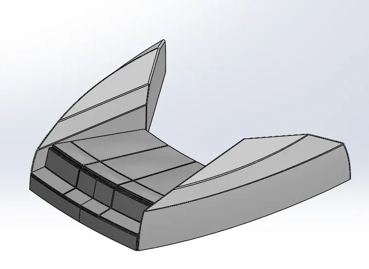
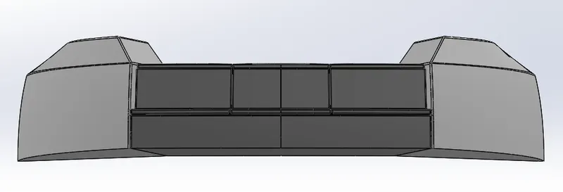
The Front seat is half surface and half solid model. It combines other features used in previous models. The extra commands used in this are:
- Insert
This inserted part is the hull model but only the surface part is selected while importing. This acts as a base for all the models designed and helps in assembling as we place the model before assembling.
The seat was given an appearance of white and light grey.
7. MIDDLE SEAT
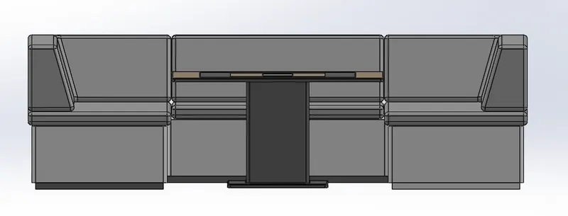
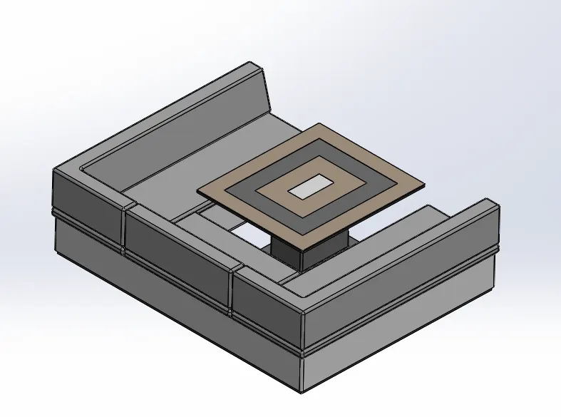
The middle seat is similar to that of front seat, but it involves more solid modelling than surface modelling.
It used features like extrude, extrude cut, fillet and chamfer.
The appearance used are white, RGB 120,120,120, RGB 190,169,146 and light grey.
8. REAR SEAT
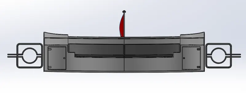
The rear is similar to front seat with combination of surface and solid modelling. New features used are:
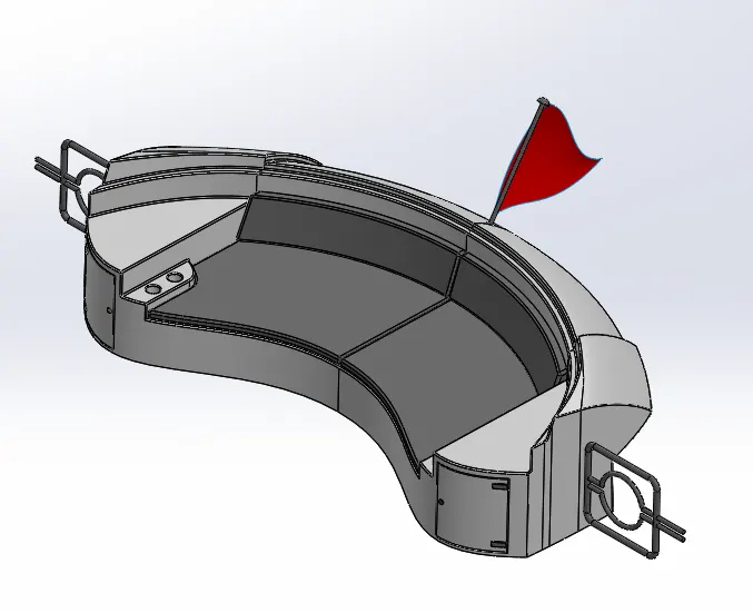
- Flag design
The flag was designed in 3d sketch where no plane or surface needs to be selected for reference and sketched in open. The loft feature was used to connect the 3d sketches and made into a flag.
The other features have been mentioned in previous steps. The appearance given to the rear seat are white, light grey, RGB 255, 255, 227, Grey and Red.
9. SUPERSTRUCTURE
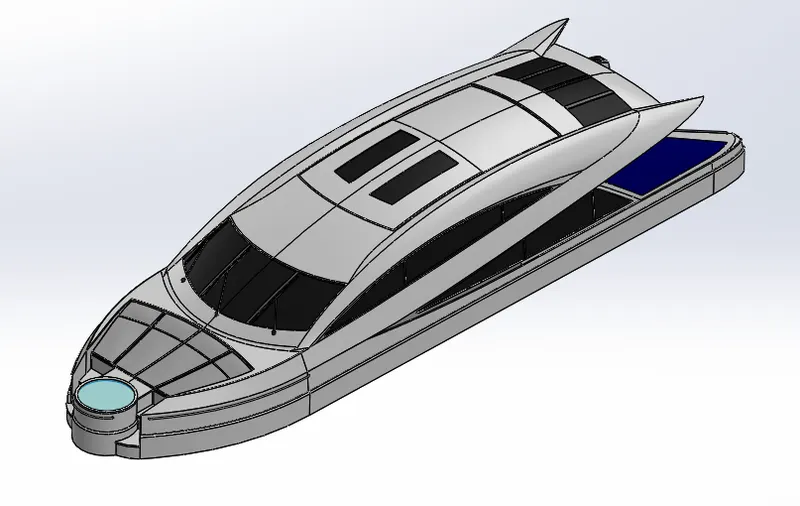
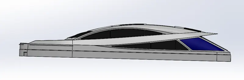
The Superstructure is 90% surface modelling and the features used are:
- Lofted Surface
- Swept Surface
- Extruded Surface
- Extend Surface
- Ruled Surface
- Filled Surface
- Trim surface
- Knit Surface
- Delete face
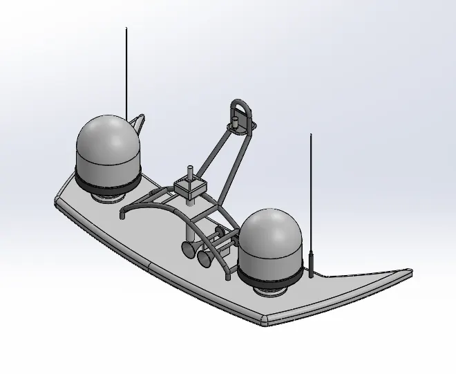
10. RADARMAST
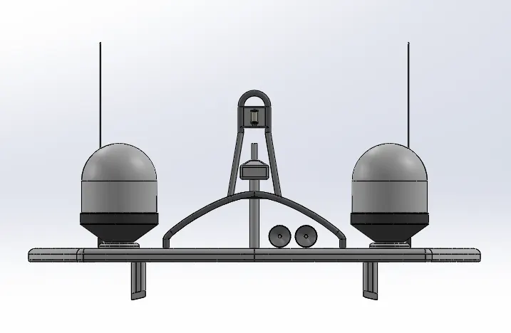
Radar mast is a solid body with solid modelling. The features used are:
- Extrude Boss/Base
- Chamfer/Fillet
- Extrude Cut
11. ASSEMBLY
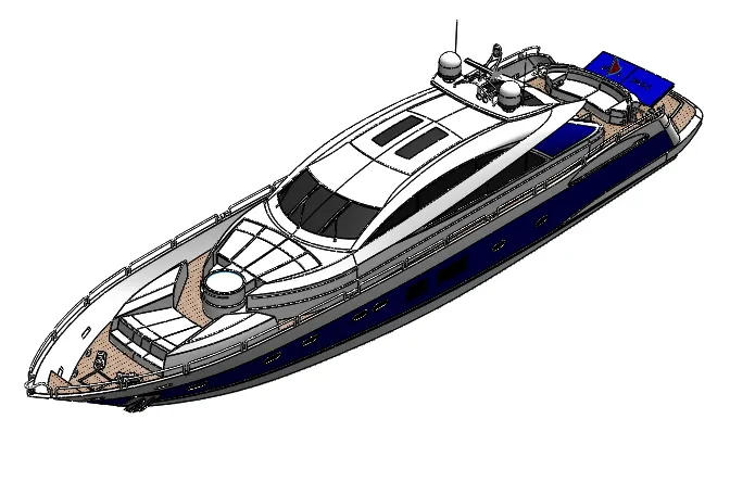
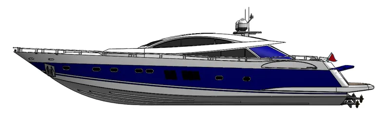
The assembly doesn’t require a lot of mates because we started each model with insert part feature and used the hulls surface as a base plane. So, all we have to do is import the part inside the assembly and it sits in its respective place. The garage door needs to be mated to show as it is opening.
12. RENDERING
The camera view is set in Photoview 360 and Solidworks Visualize is opened. The Yacht model is loaded inside and a picture of sea is loaded in as the background image for the Yacht. The model is rendered in various positions.