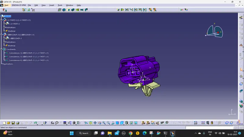
Wiring harness design in CATIA V5 - 3D modeling Week 2 Challenge
STEPS TO DEFINE 3D CONNECTORS AS ELECTRICAL CONNECTORS:
- Download the igs file on the TE website and open it in catia v5.
- save the file as CATPART and store it in the catalog.
- Then open in electrical part design
- Define part as a connector
- Define bundle connection point
- Define connector connection point
- Define cavity connection point
DEFINE CONNECTORS:
In the mechanical part design place points and axis in the part design.
the x-axis should be in the locking position
y-axis should be in the path(coincides)
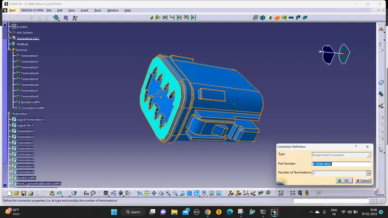
then use define as a connector command to define it in the EPD(ELECTRICAL PART DESIGN)
then enter how many terminals are there (ex:8).
DEFINE BUNDLE CONNECTION POINT:
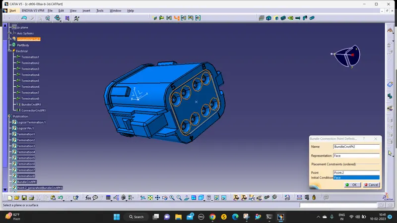
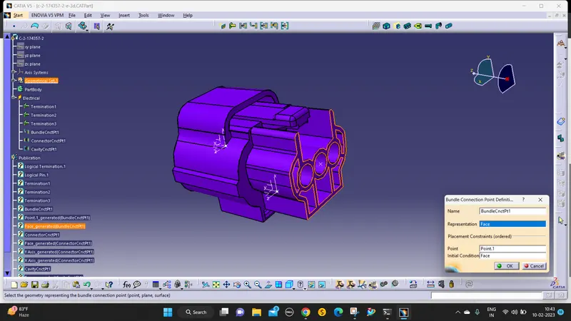
the wire connecting part is a bundle entry connection.
The Point is placed before the mechanical part design that is used as a bundle connection point.
the point is placed in the middle of the face on the bundle entry side.
then define it using the bundle connection point command.
CONNECTOR CONNECTION POINT:
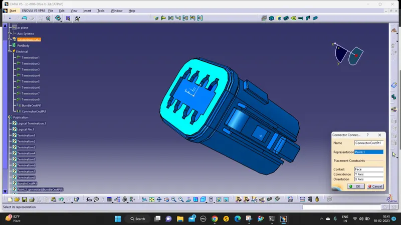
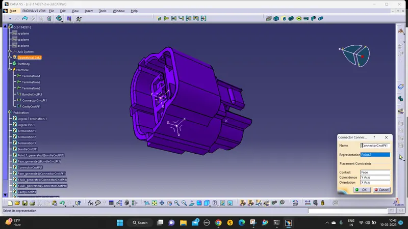
The point and axis that is placed in the mating point is the connector connection point.
then define it using the connector connection point command.
CAVITY CONNECTION POINT:
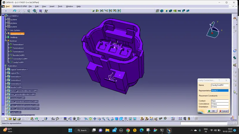
The point should be in the locking face and the axis as follows the connectors' connection points.
1. Deutsch DT06-08SA
define as a connector:
define bundle connection point:
define connector connection point:
2. Tyco 174357-2
first, define the connector And define connector connection point:
define cavity connection point:
define bundle connection point:
3. Tyco 85229-1
define as cavity point:
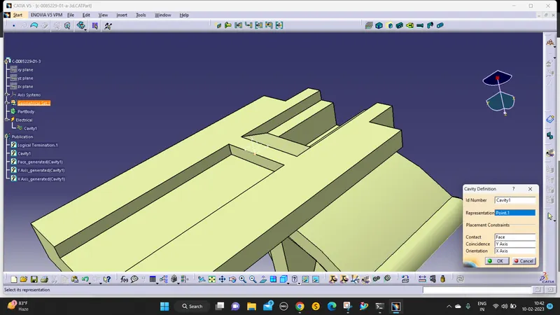
cavity and clip locking in electrical assembly design