Wiring harness design in CATIA V5 - 3D modeling Week 2 Challenge
Wiring harness design in CATIA V5:
Defining Connector (Deutsch DT06 – 08SA), Connector (Tyco 174357-2) & Mounting Clip (Tyco 85229-1):
-
AIM:
- To download the following connectors & Connector clip cad data from given link & define it as Electrical Connector using Electrical Part design Workbench. Define all the necessary properties to Connectors & Clip.
-
DEFINING THE NECESSARY PROPERTIES TO CONNECTOR & CLIP:
In this challenge, the primary aim is just to define the connector with its electrical properties such as CONNECTOR CONNECTION DEFINITION, BUNDLE CONNECTION DEFINITION, and CAVITY CONNECTION DEFINITION.
Connector (Deutsch DT06 – 08SA):
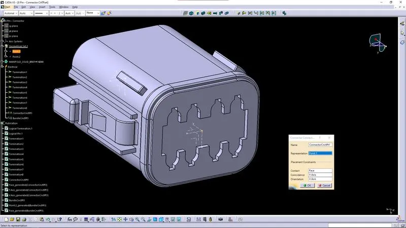
↑ The above image shows the CONNECTOR CONNECTION DEFINITION by creating a mid point of the connector face, placing an axis system which the X axis is rotated by 90°.
- Point as a Representation
- Contact being the outer most face of the connector.
- Coincidence being the Y axis in the Axis System.
- Orientation being the X axis in the Axis System.
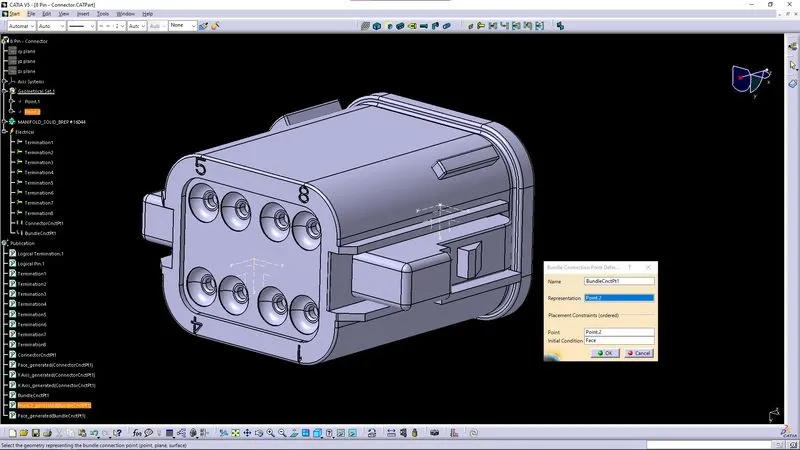
↑ The above image shows the BUNDLE CONNECTION DEFINITION by creating a mid point of the bundle face, placing an axis system which the X axis is rotated by 90°.
- Point as a Representation
- In the placement constraints, point is selected as the same.
- Initial condition being the face of the bundle connection.
- - -
Connector (Tyco 174357-2):
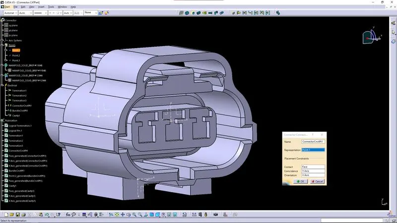
↑ The above image shows the CONNECTOR CONNECTION DEFINITION by creating a mid point of the connector face, placing an axis system which the X axis is rotated by 90°.
- Point as a Representation
- Contact being the outer most face of the connector.
- Coincidence being the Y axis in the Axis System.
- Orientation being the X axis in the Axis System.
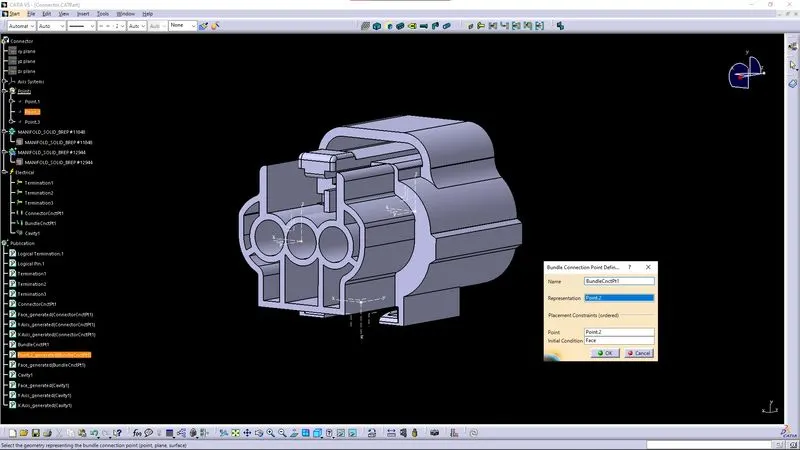
↑ The above image shows the BUNDLE CONNECTION DEFINITION by creating a mid point of the bundle face, placing an axis system which the X axis is rotated by 90°.
- Point as a Representation
- In the placement constraints, point is selected as the same.
- Initial condition being the face of the bundle connection.
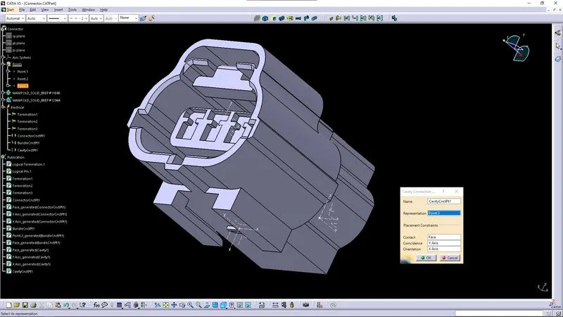
↑ The above image shows the CAVITY CONNECTION DEFINITION by creating a mid point of the cavity contact face, placing an axis system which the X axis is rotated by 90°.
- Point as a Representation
- In the placement constraints, point is selected as the same.
- Initial condition being the face of the bundle connection.
- - -
Mounting Clip (Tyco 85229-1)
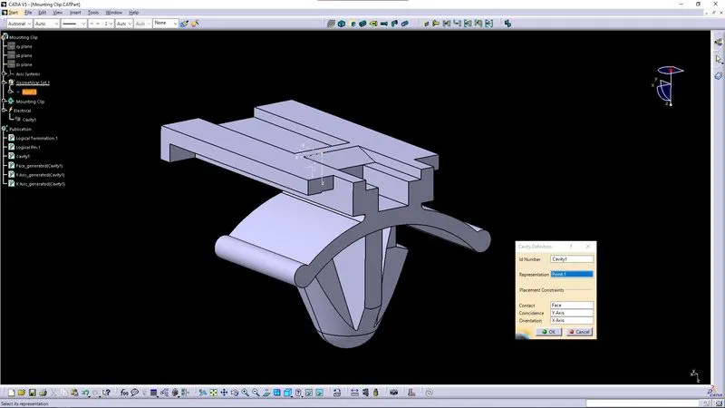
↑ The above image shows the CAVITY DEFINITION by creating a mid point of the cavity contact face, placing an axis system which the X axis is rotated by 90°.
- Point as a Representation
- Contact being the face of the cavity.
- Coincidence being the Y axis in the Axis System.
- Orientation being the X axis in the Axis System.
- - -
CONCLUSION:
- The Connectors & Connector clip given from the link is succesfully defined as Electrical Connector using Electrical Part design Workbench.
- Connectors & Clip are defined with all the necessary properties to begin with.
- - -