Week 8 - Challenge 4 - Bumper
TITLE: BUMPER DESIGN
-
AIM:
To create the Plastic Bumper component through the given Class-A surface. To begin with, the tooling axis for the given Class-A Surface should be created meeting the requirements of the draft angle and at the end perform the Draft analysis on the model.
REPORT:
This report demonstrates the design of an Automotive Plastic Component – Front Bumper (Plastic) using industry principles such as Draft angles, Draft Analysis, Determining and implementing of Tooling Axis, Class A, Class B and Class C surfaces. The component is designed using Surface Design and Solid Design techniques in CATIA V5.
Bumpers of automobiles have been made of a combination of Polycarbonate (PC) and Acrylonitrile Butadiene Styrene (ABS) called PC/ABS. It's also well-suited to heavy-duty applications, so it can be used for automotive body parts, too. Plastic used in cars, like PC/ABS, helps the body absorb and redistribute energy during an impact, keeping passengers safe. And also completely aesthetic.
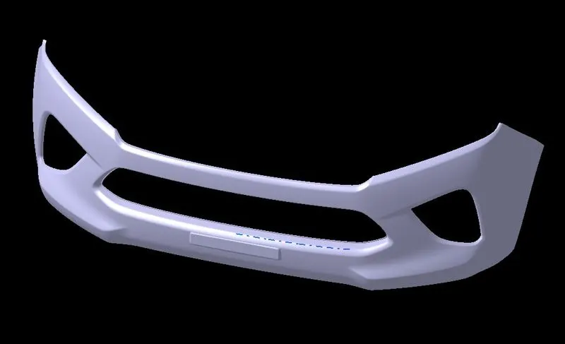
↑ BUMPER ↑
The terms are briefly explained below:
Draft:
- Draft is an angular tapering given at the design stage to every Plastic Component that has to be manufactured.
- It is given in the direction of the Mold Movement.
- The Draft allows the parts to release easily from the mold without creating friction between the surface of component and the core and cavity plates.
- When a Plastic component cools down inside the mold, the natural tendency of it is to shrink and attach to the core or cavity half.
- The movement of mold opening causes friction on the walls of the component as well as the core/cavity blocks.
- This reduces the life of the mold as well as the component itself.
- The component may also have rough surface finish as well as weak structure due to this.
- This problem can be solved by giving draft to the component.
- Most applications require minimum draft angles of around 0.5º to 1º , however 3º draft angles are widely accepted for cost saving purpose.
- 7º Draft angles are given to textured surfaces like Instrument Panels.
- Minimum possible draft angles are given to screw bosses, ribs and stiffeners due to their critical nature.
-
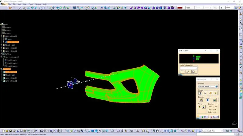
↑ DRAFT ANALYSIS FOR CLASS A SURFACE ↑
Draft Analysis:
- Draft Analysis is a tool in CATIA which identifies the zones which deviates from the specified values of angles along a defined draft direction using colour codes.
- Draft analysis is the first step performed after receiving the Class A of the component.
- Draft analysis should be passed in order to make the plastic component manufacturable.
- Acceptable draft angles are used as range for draft analysis.
For Analyzing the Draft of the Class A Surface:-
- Change View Mode Customization to Material mode
- Go to INSERT ---> ANALYSIS ---> FEATURE DRAFT ANALYSIS and move the compass to the Tooling Axis.
- Change the range to 0º to 2.9º . Apply the settings as shown in Figure.
- As shown the target area has 0º draft angle which was the concerned face, since it's a flat surface.
- Thus, it passes the criteria of having suitable draft and the Class A can be further designed into a solid plastic component and manufactured.
-
Tooling Axis:
- Tooling Axis is the direction in which the Mold opens and closes. Part Drafts are given along this axis.
- Identify faces which can potentially create problems while manufacturing.
- Surfaces at angles along a desired Tooling Axis.
- Extract a plain surface and create a point on its center for Axis system creation.
- In this case X axis can be a possible Tooling Axis Direction.
-
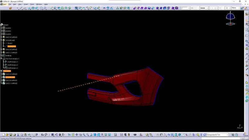
↑ TOOLING AXIS ↑
-
Class- A Surface:
- In automotive design, a class A surface is any of a set of freeform surfaces of high efficiency and quality.
- It is the visible aesthetic surface of any automotive component.
- Class A surface refers to those surfaces which are visible and abide to the physical meaning, in a product.
- This classification is primarily used in the automotive and increasingly in consumer goods industry.
- It is a requirement where aesthetics has a significant contribution.
- For this reason, the exterior of automobiles is deemed Class-A.
Class- B Surface:
- Class B surfaces are Engineering Surfaces which are invisible to the eyes or often on the back side of the Class A surfaces.
- It is mainly the thickness of the component or Class A.
- These surfaces need to be designed as per the Class A surface i.e., the continuity, thickness of the component, functionality etc should be maintained.
- These surfaces include the main engineering features such as Screw bosses, Ribs, Snaps, Stiffeners and fixations.
- B surfaces also do not contain any aesthetic styling content and textures since it is not visible to eyes.
Class- C Surface:
- Class C surfaces are connectors between Class A and B surfaces.
- This surface connects both A and B surfaces along the Tooling Axis.
- It contains the draft as per the design.
- It is basically the thickened surface between both A and B surface.
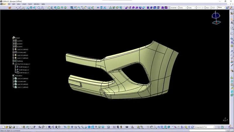
↑ CLASS A, B & C SURFACES ↑
-
Class B Surface:
- Offset the relevant surfaces from Class-A surface, the offset length is 3mm since the thickness is 3mm.
- Here the selected faces consist of Front Bumper surface, Walls and the Base surface.
- Offset these surfaces is shown below.
→ Starting with the Front Grille Section.
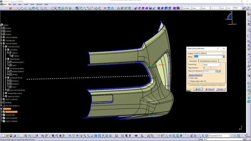
↑ Offset CLASS A SURFACE to create CLASS B SURFACE ↑
- Offset the Class A Surface by 3mm to create the Class B Surface.
- After offsetting the surface, some open portions are left.
- To fill in those open portions, Extract the required portions using "Multiple Extract". Split the necessary portions after extracting.
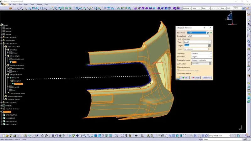
↑ Extrapolate - CLASS B SURFACE ↑
- Later after Extracting and Splitting the necessary surfaces, using "Extrapolate" select the edges from the offset to create a boundary to extrapolate to a required length of 10mm with curvature continuity, tangent extremity on a tangency propagation.
- After extrapolation, trim the excess portion.
- Creating fillets.
- Create Fillets while maintaining the part thickness between the Class A and Class B surfaces.
- The Value of Fillet is given by the equation (B surface fillet = A surface fillet ` Thickness of the Part).
- The sign + or – must be decided so as to maintain the part thickness which in this case is 3mm.
- The fillet is 3.5mm
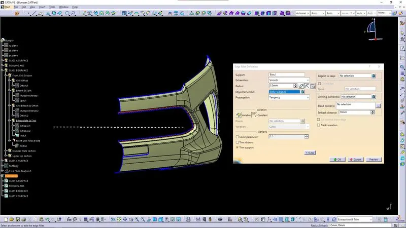
↑ Fillet - Front Grille Section - CLASS B SURFACE ↑
The Front Grille section is completed. Now, moving on to the Number Plate section.
-
→ Now, Number Plate Section.
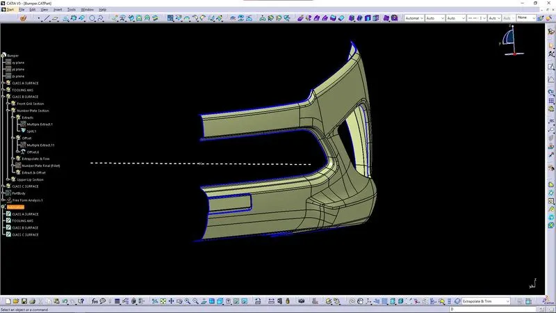
- Extract the necessary portion from Class A surface using "Multiple Extract", while extracting avoid the fillet edges.
- Using the extracted portion, split the portion from the Class A surface. With the splitted portion, give an offset of 3mm inward.
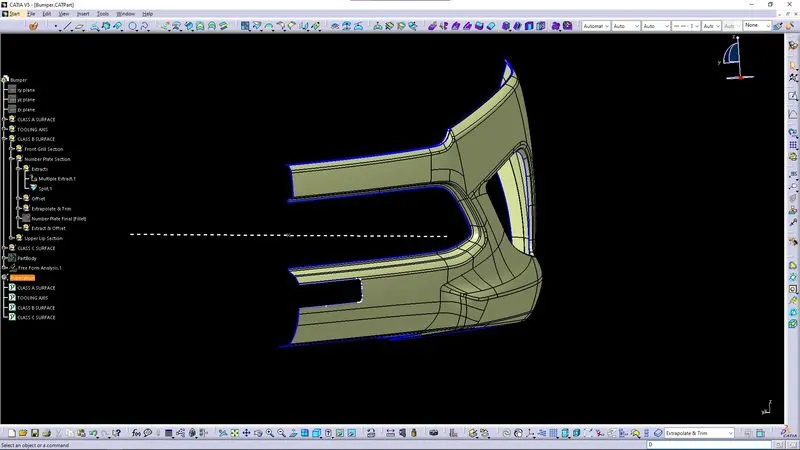
- Extrapolate the surface edges of the number plate section and trim the excess portion for a complete and integrated finish.
- Creating fillets.
- Create Fillets while maintaining the part thickness between the Class A and Class B surfaces.
- The Value of Fillet is given by the equation (B surface fillet = A surface fillet ` Thickness of the Part).
- The sign + or – must be decided so as to maintain the part thickness which in this case is 3mm.
- The fillet is 3.5mm
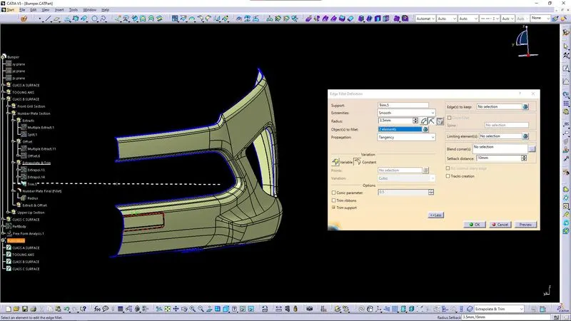
↑ Fillet - Number Plate Section - CLASS B SURFACE ↑
The Number Plate section is completed. Now, moving on to the Upper Lip section.
-
→ Now, Upper Lip Section.
- Extract the necessary portion from Class A surface using "Multiple Extract", while extracting avoid the fillet edges.
- Using the extracted portion, split the portion from the Class A surface. With the splitted portion, give an offset of 3mm inward.
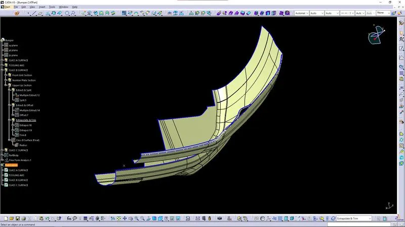
- Extrapolate the surface edges of the number plate section and trim the excess portion for a complete and integrated finish.
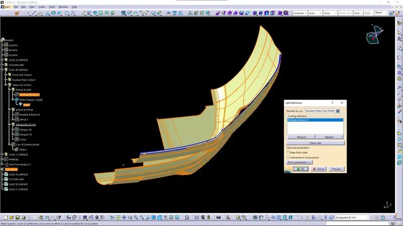
- Creating fillets.
- Create Fillets while maintaining the part thickness between the Class A and Class B surfaces.
- The Value of Fillet is given by the equation (B surface fillet = A surface fillet ` Thickness of the Part).
- The sign + or – must be decided so as to maintain the part thickness which in this case is 3mm. The upper lip section measure a radius of 3.668mm so the fillet is given by subtracting the thickness.
- The fillet is 0.668mm
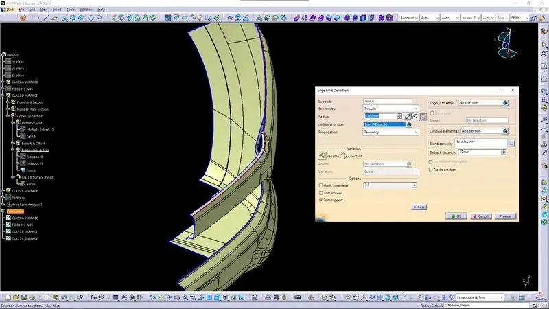
↑ Fillet - Upper Lip Section - CLASS B SURFACE ↑
The Upper Lip section is completed. Now, moving on to Class C Surface Creation.
-
Class C Surface:
- Using the Boundary feature, the surface edges of Class B Surface and created upto the vertexes of limit of both end point.
- Using Boundary Lines, Sweep option is carried on to create a draft length extension (5mm) and draft angle (90°).
- After the Sweep Operation, the complete surface edges are joined together using Join option. And then trim the excessive portions to obtain the desired outcome.
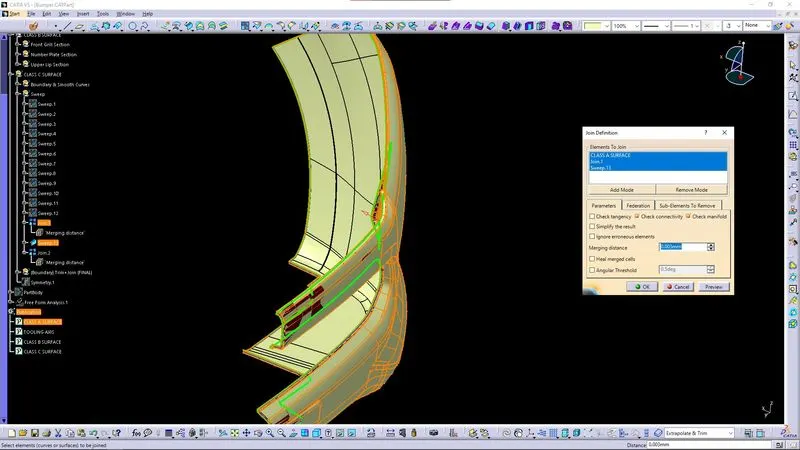
↑ Sweep - CLASS C SURFACE ↑
- After the Sweep Operation, the complete surface edges are joined together using Join option. And then trim the excessive portions to obtain the desired outcome.
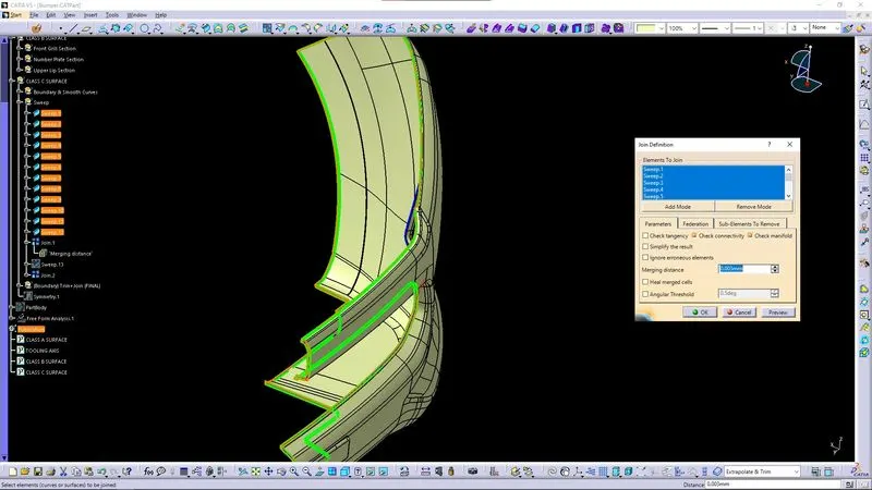
↑ Join - CLASS C SURFACE ↑
-
Draft Analysis of Class B Surface:
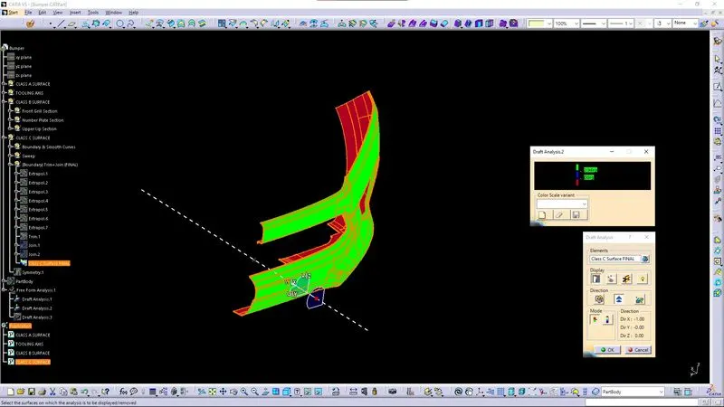
↑ DRAFT ANALYSIS FOR CLASS C SURFACE ↑
Draft Analysis:
- Draft Analysis is a tool in CATIA which identifies the zones which deviates from the specified values of angles along a defined draft direction using colour codes.
- Draft analysis is the last step performed after receiving the Class C of the component.
- Draft analysis should be passed in order to make the plastic component manufacturable.
- Acceptable draft angles are used as range for draft analysis.
For Analyzing the Draft of the Class C Surface:-
- Change View Mode Customization to Material mode
- Go to INSERT ---> ANALYSIS ---> FEATURE DRAFT ANALYSIS and move the compass to the Tooling Axis.
- Change the range to 0º to 2.9º . Apply the settings as shown in Figure.
- As shown the target area has 0º draft angle which was the concerned face, since it's a flat surface.
- Thus, it passes the criteria of having suitable draft and the Class A can be further designed into a solid plastic component and manufactured.
-
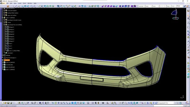
→ After the creation of Class C Surface, for the complete bumper design. Symmetry option is done by taking the reference plane (ZX Plane) and the desired element.
-
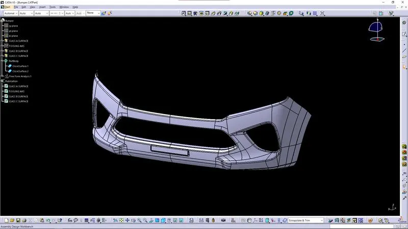
Closed Body Creation:
The final product is achieved by using the Part Design workbench to make it a closed surface.
-
CONCLUSION:
The Design of Automotive Plastic Component – Bumper from Class A is completed using concepts of Draft angle, Draft Analysis for Class A and Final enclosed surface, Tooling Axis creation and implementation, Class B and Class C creation and conversion to a solid part.
- - -