Wiring harness design in CATIA V5 - 3D modeling Week 2 Challenge
AIM:
- To define Electrical properties of the given components.
OBJECTIVE:
- To download the above CAD data of the parts from the given source.
- To define the Electrical properties correctly.
- To create catalogues of the components so that it can be used later.
SOLUTION METHODOLGY:
- PART - 1: DEUTSCH DT06 - 08SA:
Step - 1:
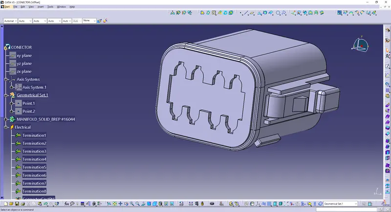
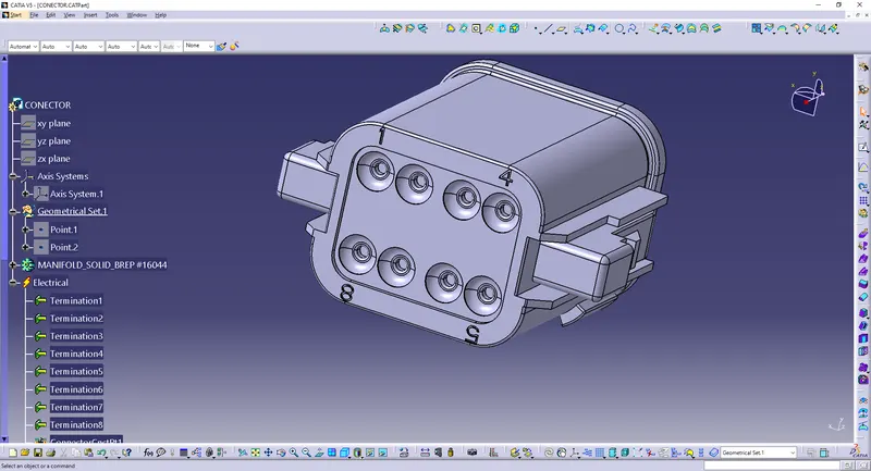
- To identify the Connector Side and the Bundle Side.
CONNECTOR SIDE:
BUNDLE SIDE:
Step - 2:
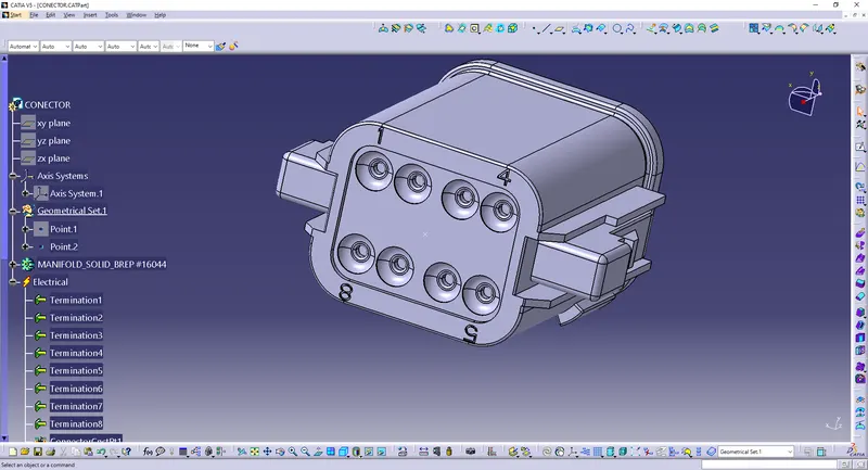
- To create a mid-point on the bundle side in the Part Workbench to define the Bundle connection properties.
Step - 3:
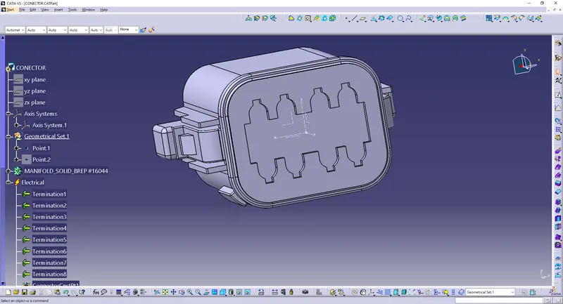
- To create a mid-point at the Connector side in the Part Workbench.
- To create an axis system through the point.
- Define the axis as:
- X- axis - Towards the locking side
- Y- Axis - Normal to the connector face

Step - 4:
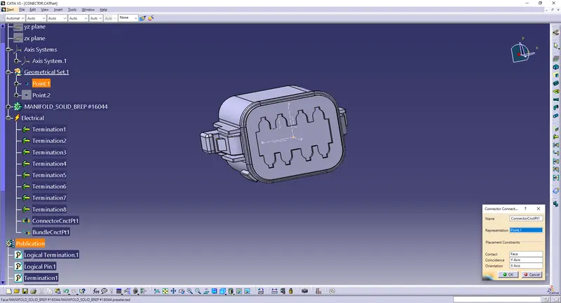
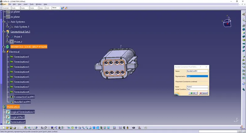
- Go to the Electrical Part Design Workbench to define the Connector connection point and Bundle connection point.
Step - 5:
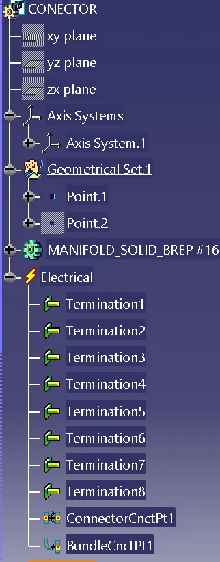
- First define the Connector and the number of Termination.
- Then define the Connector Connection Point.
- And then define the Bundle Connection Point.
CONNECTOR CONNECTION POINT:
BUNDLE CONNECTION POINT:
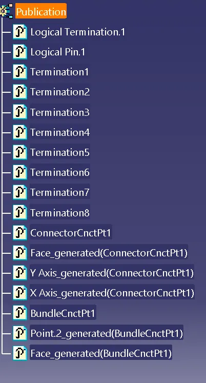
TREE STRUCTURE:
- PART - 2: TYCO 174357 - 2:
Step - 1:
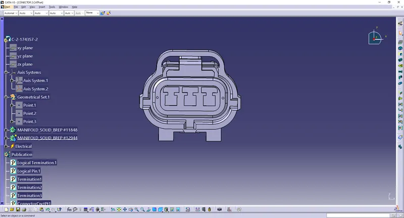
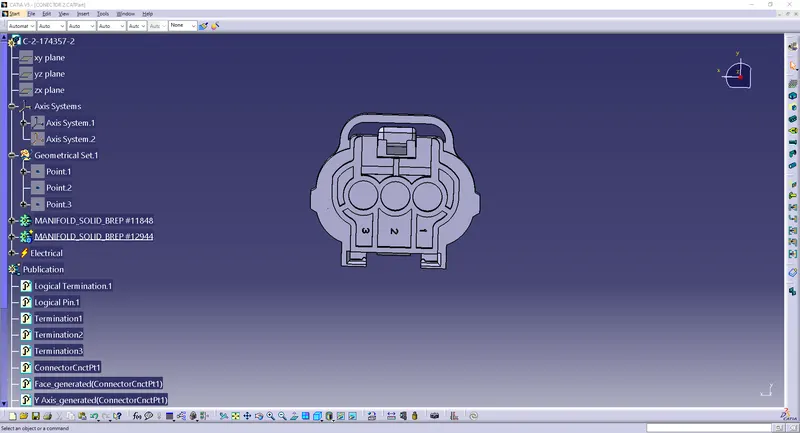
- To identify the Connector Side and the Bundle Side.
CONNECTOR SIDE:
BUNDLE SIDE:
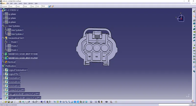
Step - 2:
- To create a mid-point on the bundle side in the Part Workbench to define the Bundle connection properties.
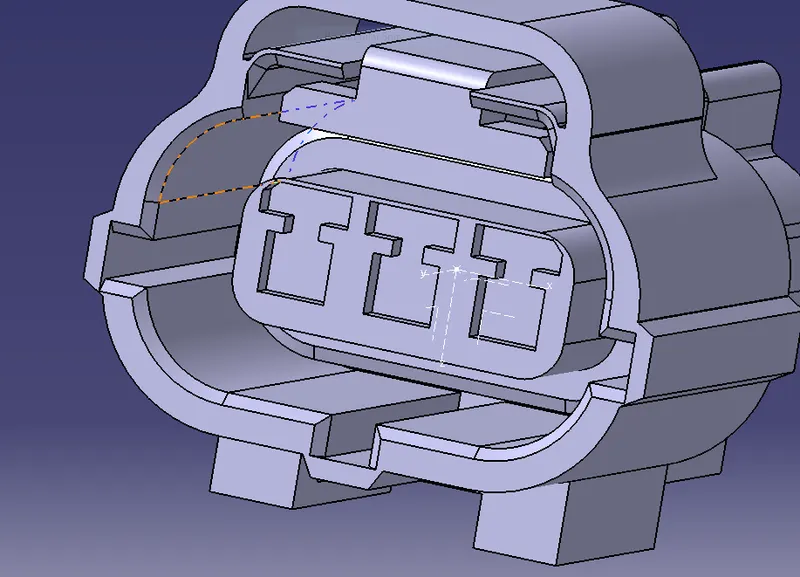
Step - 3:
- To create a mid-point at the Connector side in the Part Workbench.
- To create an axis system through the point.
- Define the axis as:
- X- axis - Towards the locking side
- Y- Axis - Normal to the connector face
Step - 4:
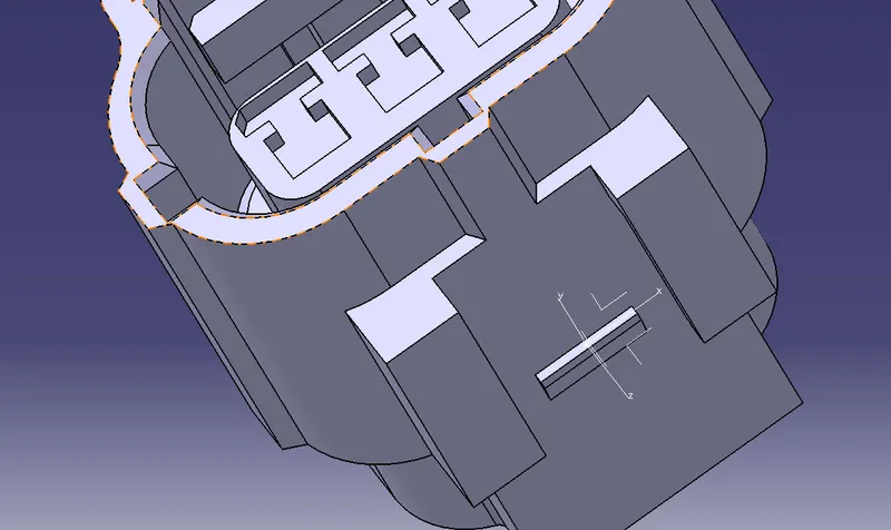
- Create a point for the Mounting clip at the required cavity position and create an axis system through the point for the cavity clip.
Step - 5:
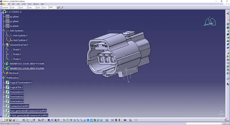
- Go to the Electrical Part Design Workbench to define the Connector connection point and Bundle connection point.
Step - 6:
- First define the Connector and the number of Termination.
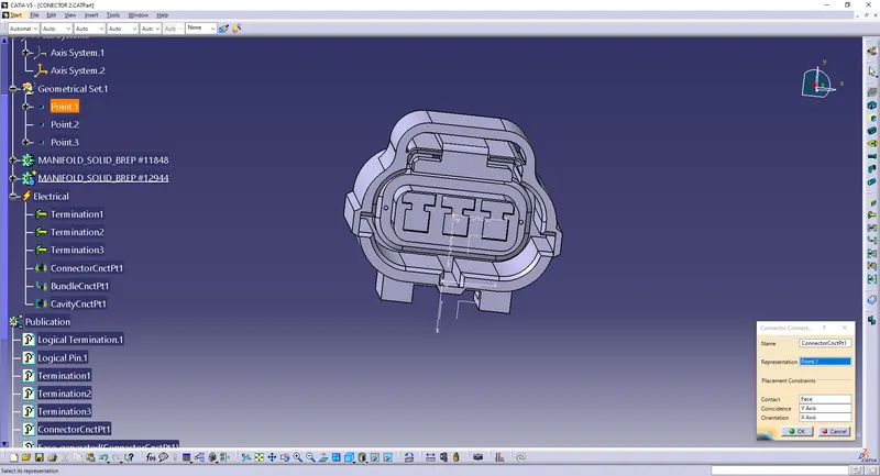
- Then define the Connector Connection Point.
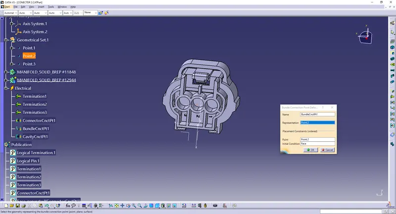
- And then define the Bundle Connection Point.
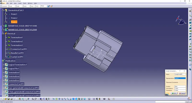
- And then define the Cavity Connection point.
CONNECTOR CONNECTION POINT:
BUNDLE CONNECTION POINT:
CAVITY CONNECTION POINT:
- PART - 3: TYCO 85229 - 1:
Step - 1:
- Create a mid-point at the location where the mounting equipment will be fitted with the connector.
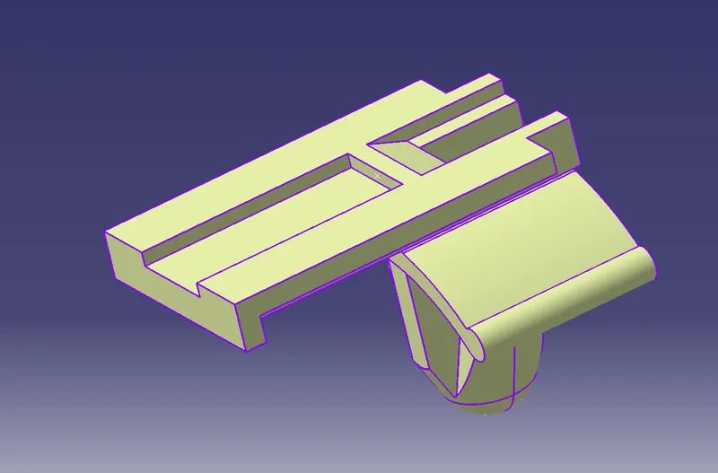
Step - 2:
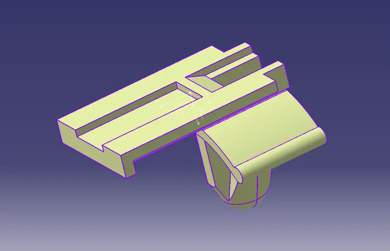
- Create an axis system through the point.
- Define the axis as per the orientation defined in the connector in which the mounting equipment will be assembled.
Step - 3:
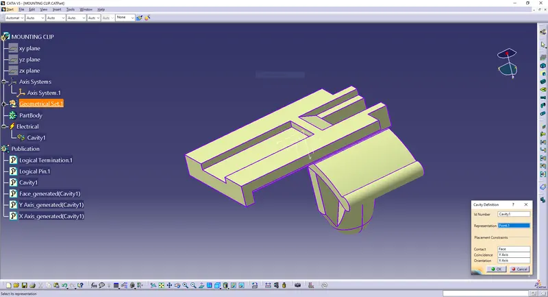
- Go to the Electrical Part Design Workbench to define the electrical properties.
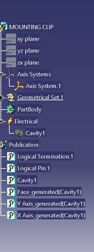
- Define the object as the Mounting equipment.
- Then define the same as cavity.
CAVITY DEFINITION:
TREE STRUCTURE:
CONCLUSION:
- From the above assignment we learnt how to define a connector and a cavity and how to define different electrical properties.
- We also learnt how to create a catalogue document and how to save the components in the catalogue document so that it can be used later.