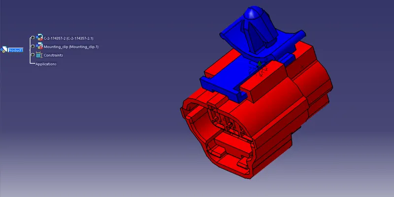
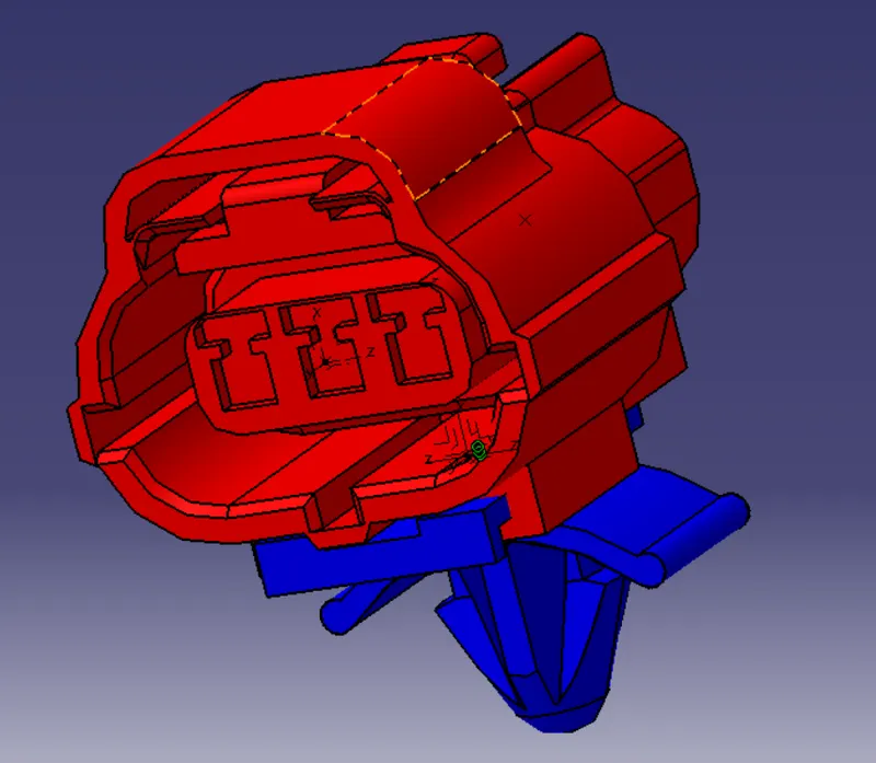
Wiring harness design in CATIA V5 - 3D modeling Week 2 Challenge
1. Deutsch DT06 – 08SA (CONNECTOR)
- Open the cad file in part design in catia V5
- Store the connector file in to connector catalogue
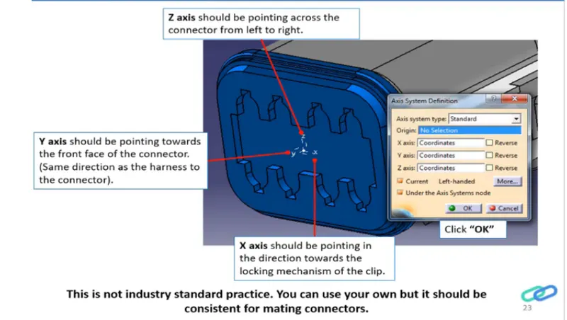
- lets create geometrical parameters such as point & axis system
- Create the connector connection point & create axis system as shown in the figure below
- Create the bundle entry point
- Now lets switch the workbench to electric part design
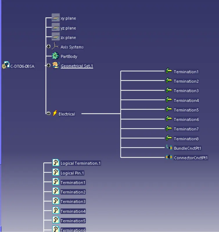
- Define the part as electric connector & input number of termination as 8 because we have 8 entry points for wire.
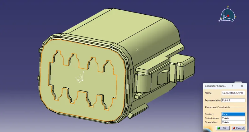
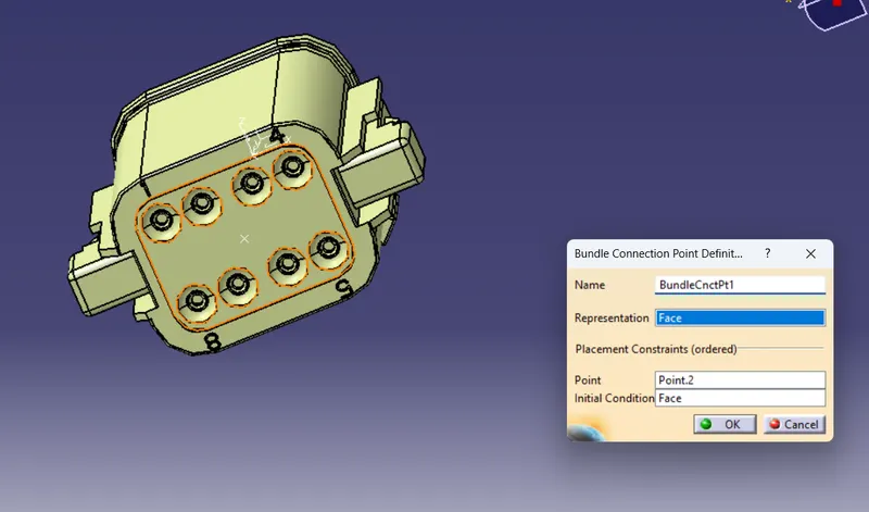
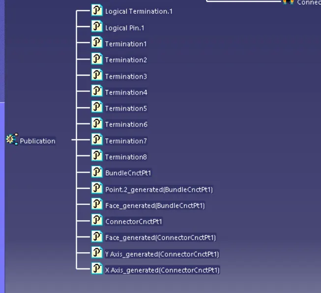
- Define bundle connection point & connector connection point
Defining connector connection point
Defining bundle connection point
2. Tyco 174357-2 (Connector)
- Open the cad file in part design in catia V5
- Store the connector file in to connector catalogue
- lets create geometrical parameters such as point & axis system
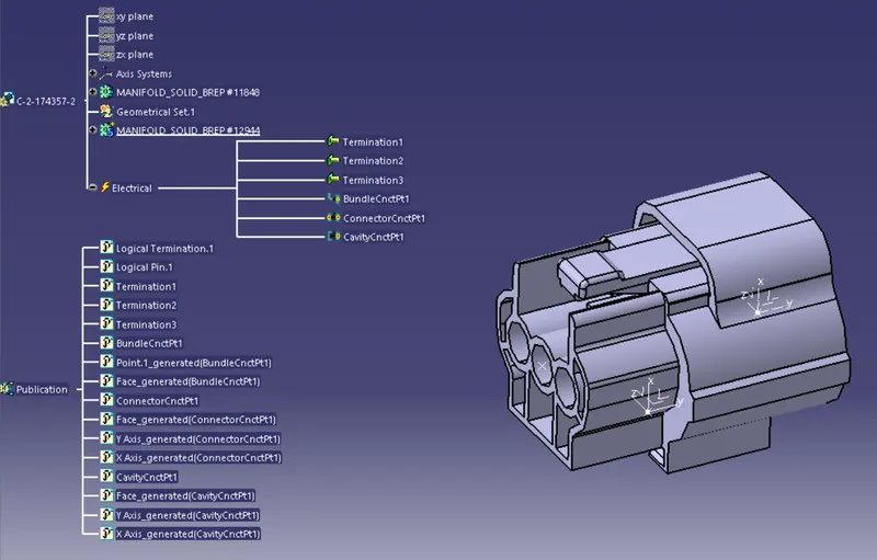
- create the connector connection point & create axis system as shown in the figure below
- create cavity connector point and its axis system
- create the bundle entry point
- Now lets switch the workbench to electric part design
- Define the part as electric connector & input number of termination as 3 because we have 3 entry points for wire.
- Define bundle connection point , connector connection point , and cavity connection point
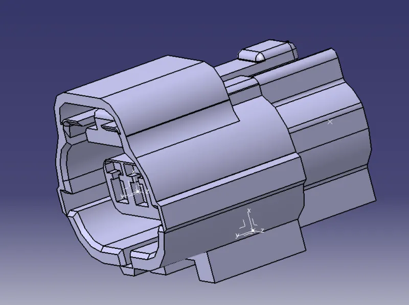
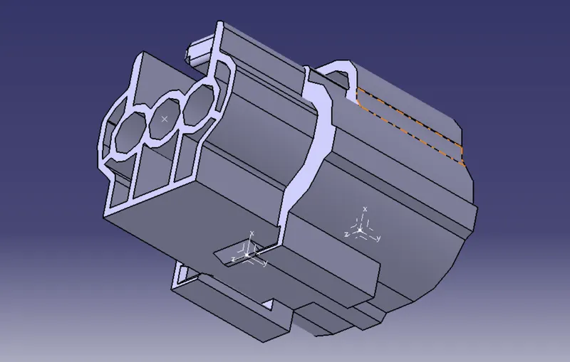
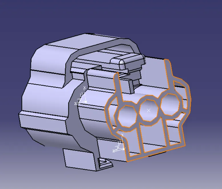
Defining bundle connection point
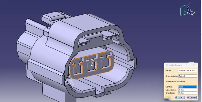
Defining connector connection point
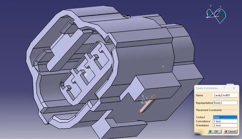
Defining cavity connection point
3. Tyco 85229-1 : (MOUNTING CLIP)
- Open the cad file in part design in catia V5
- lets create geometrical parameters such as point & axis system
- Create the cavity connection point
- Now lets switch the workbench to electric part design
- Define the part as mounting equipment
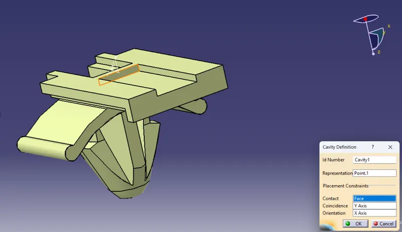
- Define the cavity connection point
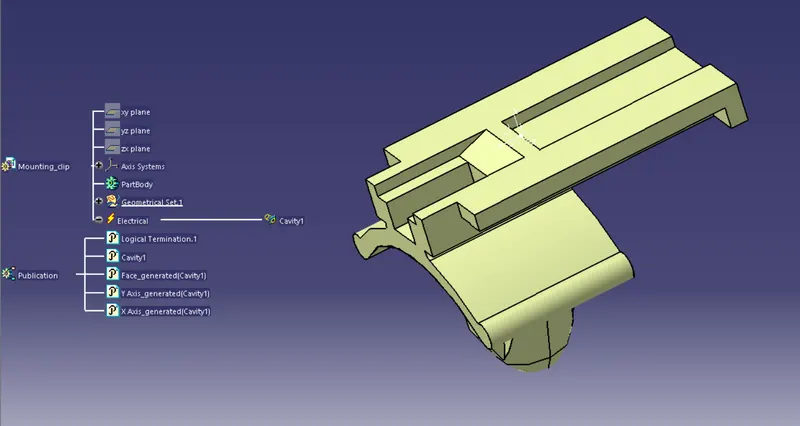
Defining cavity connection point
Electric Assembly Design
- Open the Electric Assembly design workbench
- Import Connector and mounting clip.
- click on Define Eelectric device
- select cavity and then connector to establish the connection