Wiring harness design in CATIA V5 - 3D modeling Week 2 Challenge
AIM
To Download following connectors & Connector clip cad data from given link & define it as Electrical Connector using Electrical Part design Workbench. Define all the necessary properties to Connectors & Clip.
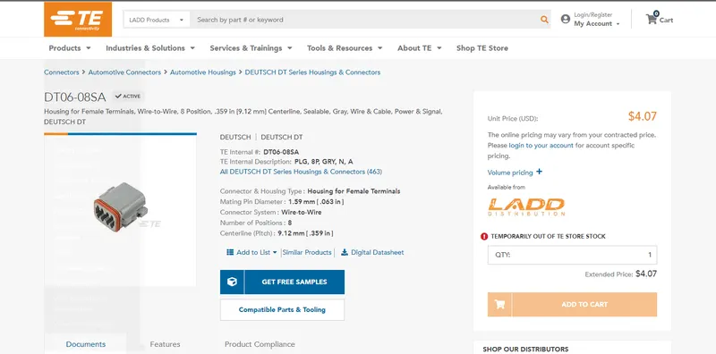
- Deutsch DT06 – 08SA ( https://www.te.com/usa-en/product-DT06-08SA.html)
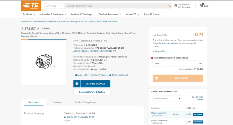
- Tyco 174357-2 (https://www.te.com/usa-en/product-2-174357-2.html?source=header-match)
- Tyco 85229-1 – (https://www.te.com/usa-en/product-85229-1.html?q=85229&source=header)
PROCEDURE
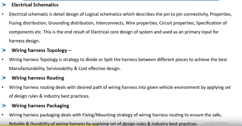
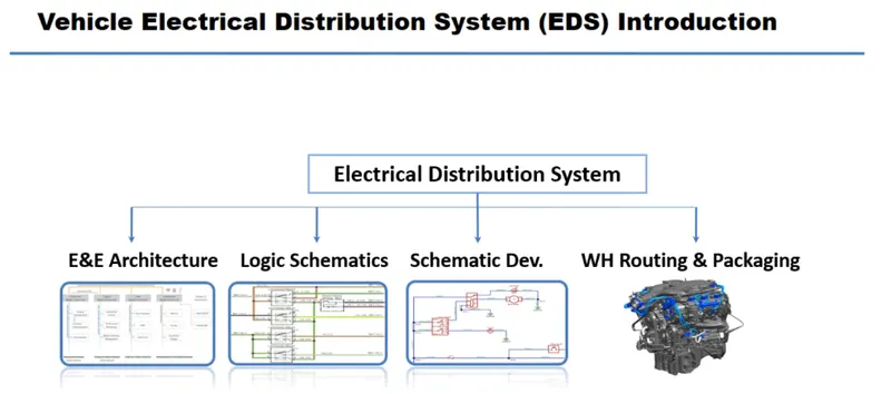
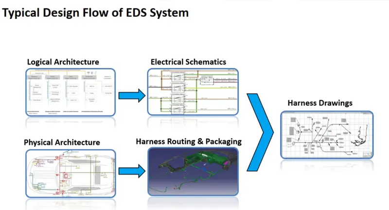
Typical design flow of EDS System.
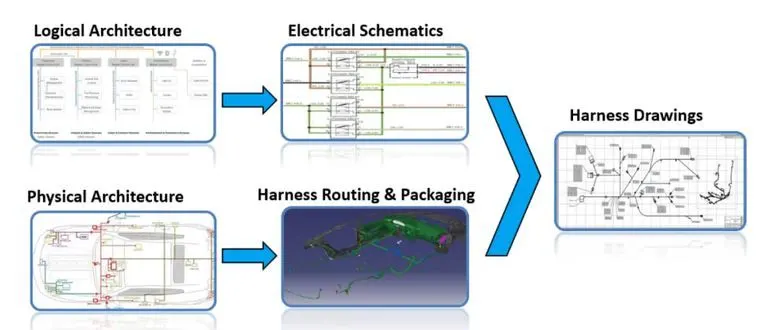
INTRODUCTION TO WIRE HARNESS
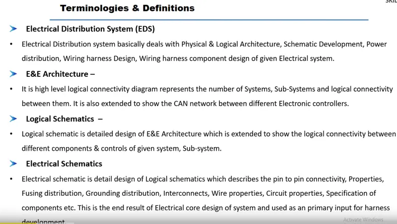
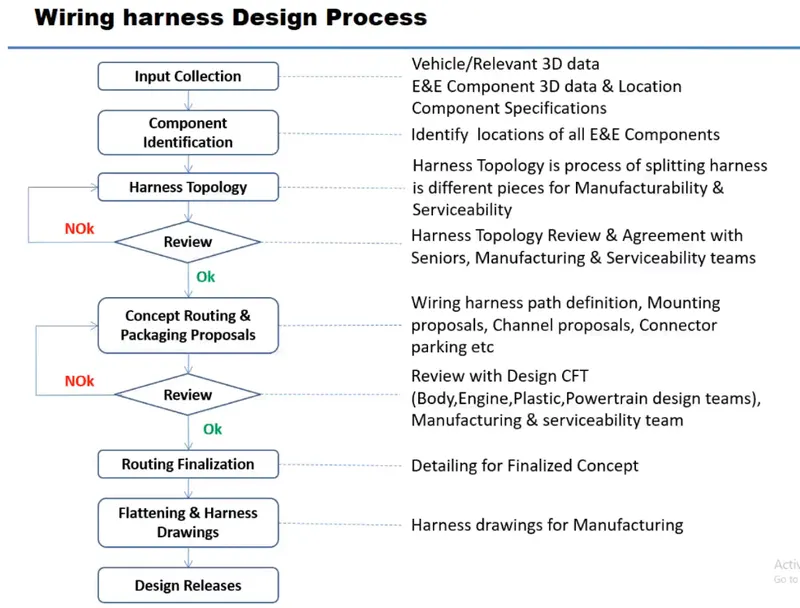
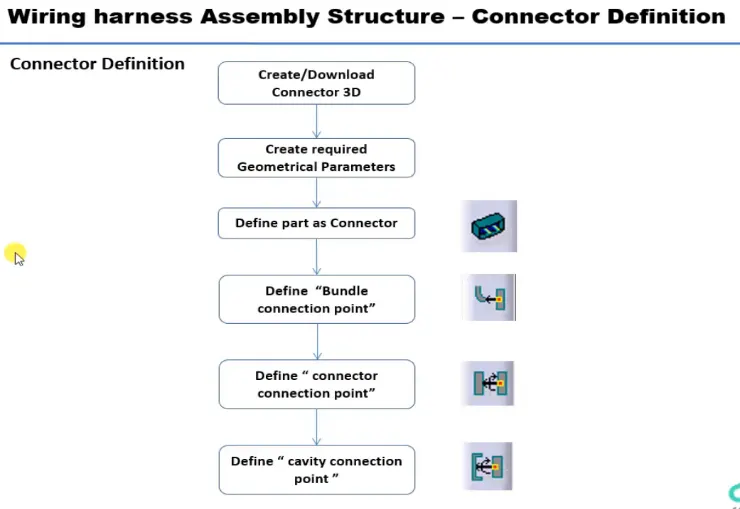
DEFINIG ELECTRIC PARAMETER FLOW CHART
Defining the connector
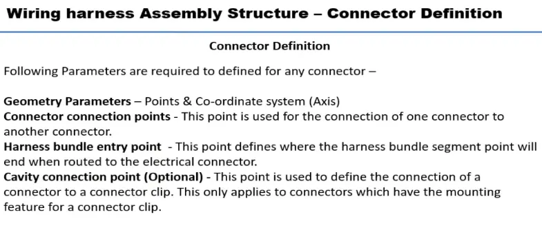
We need to define the connector by following the below steps.
- Download the connector data.
- Create required geometrical parameter.
- Define part as electrical connector.
- Define bundle connection point.
- Define connector connection point.
- Define cavity connection point.
Defining the mounting clip
- Download the clip 3d data.
- Create the geometry parameter.
- Define the part as mounting component.
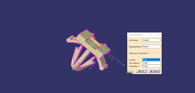
- Define the part as cavity.
Defining the connector is described below
- Downloaded the cad data from the supplier's website and the images are shown below.
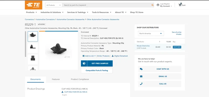
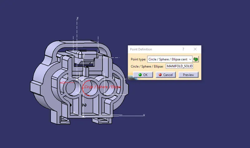
Then we have to put the axis system on the created points of the connectors with same orientation to ensure the correct assembly of the components.
- Defining the part as connector using the define connector command by selecting the command and selecting the component.
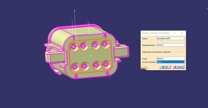
- Define bundle connection point and selecting the required input from the created geometries such as axis and points and face.
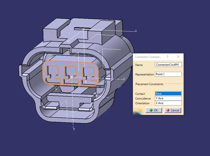
- Define the connector connection point and select the required geometry inputs for connector connection.
Creating required geometrical parameters for the connector side of DT06-08SA
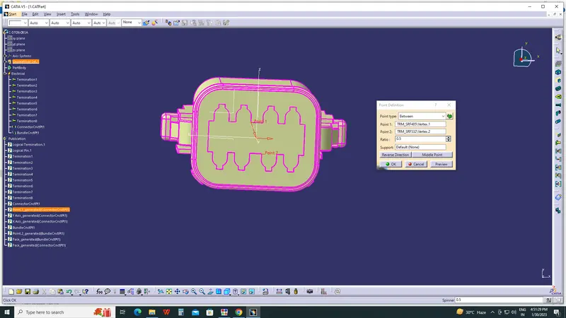
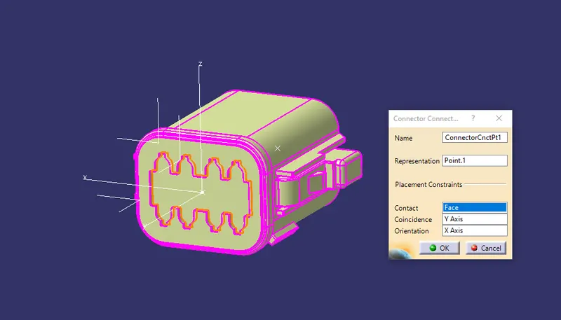
Creating required geometrical parameters for the connector side of CENTERLINE 2-174357-2
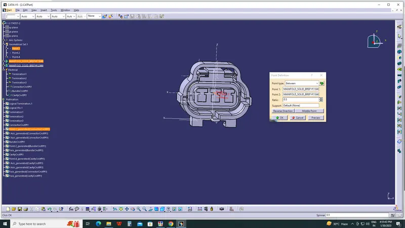
Creating required geometricalm parameters for bundle side of DT06-08SA

Creating required geometricalm parameters for bundle side of CENTERLINE 2-174357-2
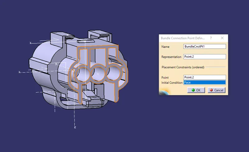
Then finally we have to define the cavity connection point, here the cavity connection point is only required when there is provision for the mounting clip is given.
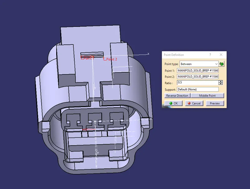
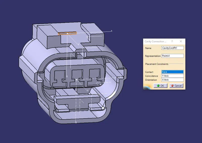
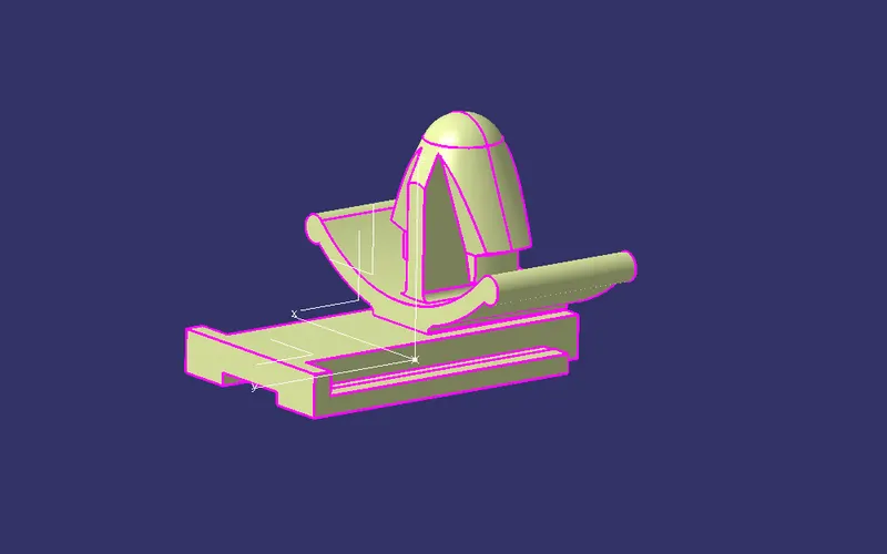
After defining the connectors we need to define the clip also, defining the clip also has various step in it.For clip we need to define it as mounting component, and select the required input needed for defining it as a mounting component.
CLIP