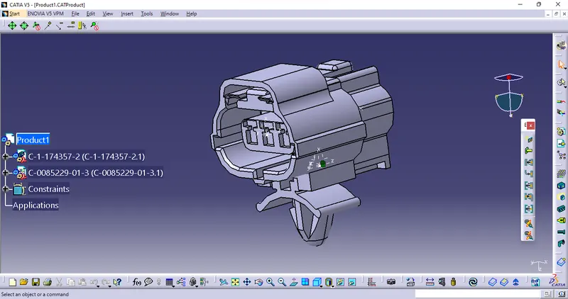
Wiring harness design in CATIA V5 - 3D modeling Week 2 Challenge
1.Deutsch DT06 – 08SA
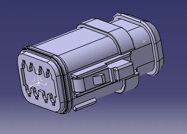
- The connector is first uploaded in the part design workbench
- We can define the parts points in the CONNECTOR CONNECTION AND BUNDLE CONNECTION.
- The axis system are placed at the CONNECTOR CONNECTION AND CAVITY CONNECTION POINTS.
- The orientation of the axis system is not specific ,we just need to follow a similar orentation for all the parts.
- Here the y-axis is in the direction of the connection,z-axis along with the clip mounting and x-axis along the bottom to top.
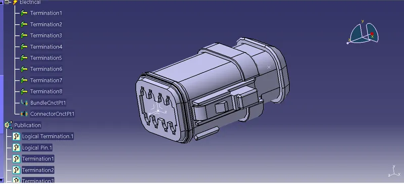
- Now we define this part as an ELECTRICAL ELEMENT/CONNECTORS,with the number of terminals.
- CONNECTOR CONECTION AND BUNDLE CONNECTION is defined in the electrical part design workbench.
2.Tyco 174357-2 and Tyco 85229-1 :
- The same process was followed for the second connector.Here we need to include the connector cavity connection point.This done to fix the clip on to the connector.
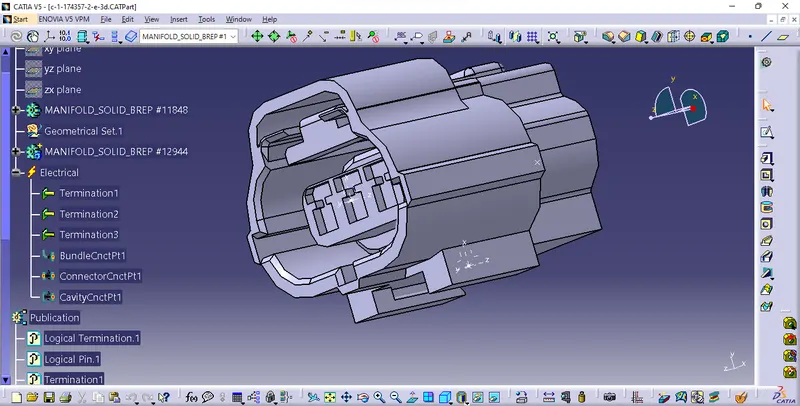
- As well as,the connector connection point created after that we have to create the cavity connection in the connector.
- For that, we have to select the connecting face for the connector connection to the another connection is clio we have mount over the connector cavity point as we created.
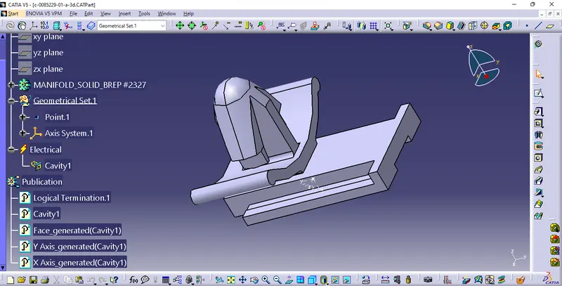
- Following that, we also created a cavity connection for the clip also as we created the cavitty point for the clip.Then,we move on to the next level.
- We have clip on the ELECTRICAL ASSEMBLY DESIGN and save the page as product 1.Then click on to the 'EXISTING COMPONENT' and select the product as we save in the file.
- The 'CONNECT ELECTRICAL DEVICE ' option is used to connect the existing two parts into the perfect assembly.