Wiring harness design in CATIA V5 - 3D modeling Week 2 Challenge
1. Defing the all parameters of connector.
We have to downlWe oad the Connector 3D design from the link given above and we should extract the file
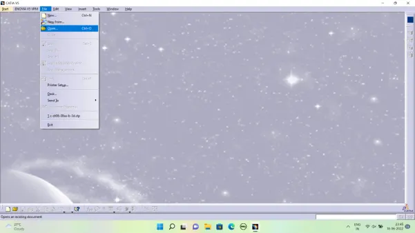
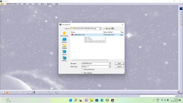
- Open the CATIA V5 click pon file > open > click on the Extracted file. The CAD Design is appered on the screen
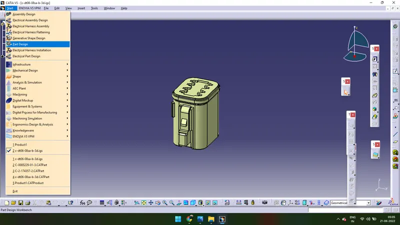
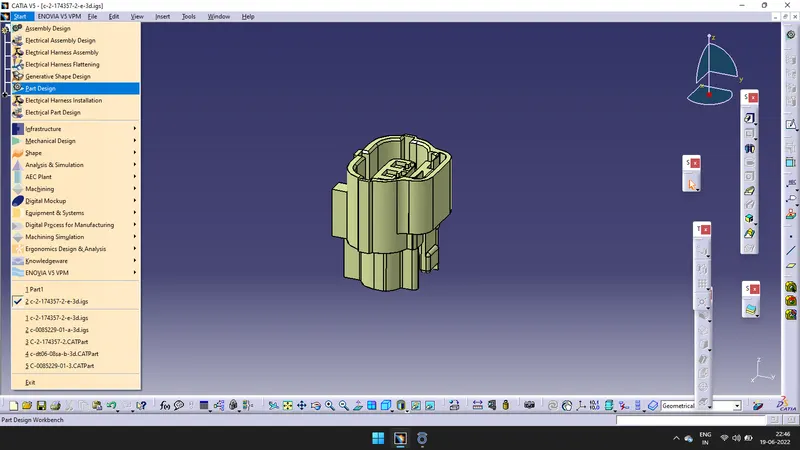
- Go to Start > Mechanical Design > Part Design.
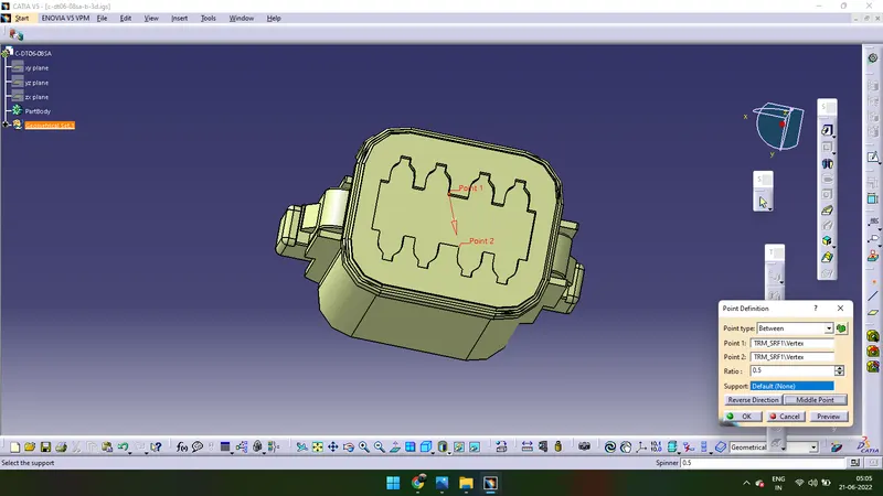
- Click on the Pointer Tool > click on Between > create two points and clink on Middle point > Ok. A point is created on connector side.
- Again we have to create another point on the bandle connection surface.
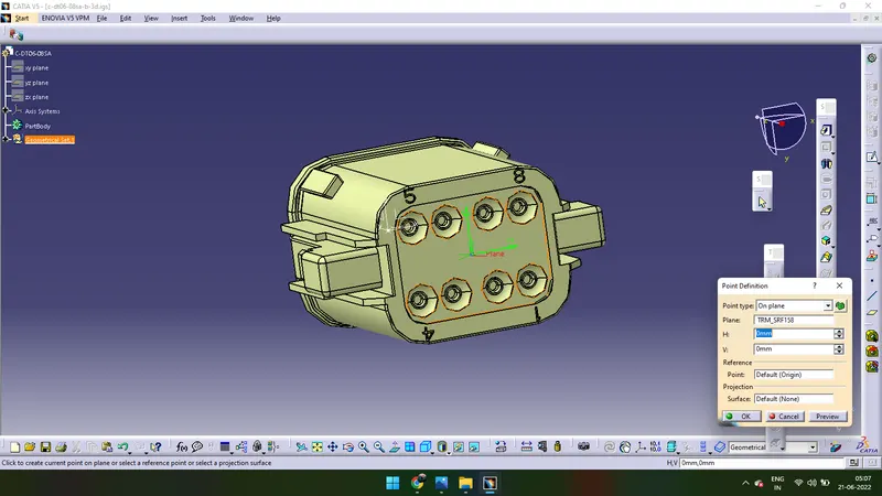
- Click on Pointer command > Select on plan > H:0 & V:0 > Ok. Point is created.
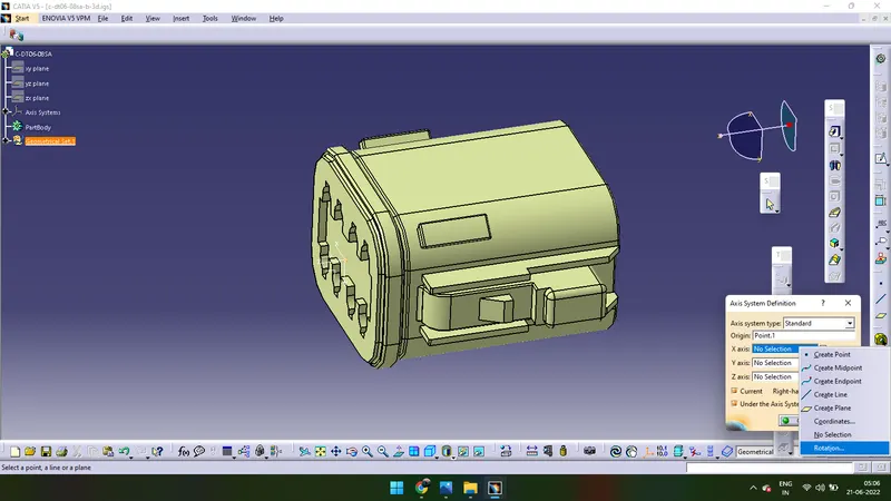
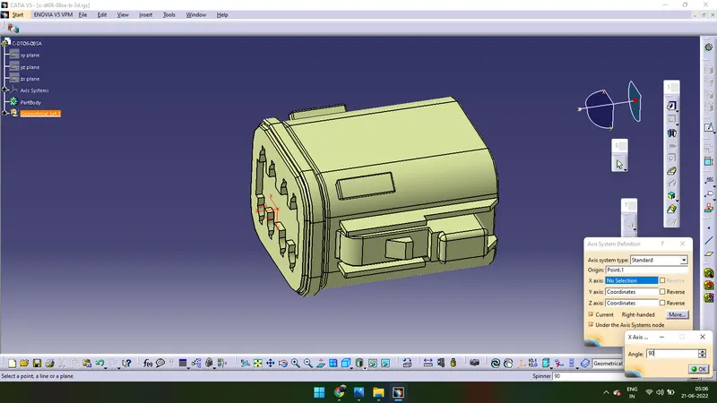
- Click on Axis command to create X,Y,Z axises. ‘X’ should be pointed towards locking mechanism (If it is in differante direction ‘right click’ go to rotation and click ‘90’, it rotates 90 Degree’s). ‘Y’ should be pointed towards the normal to the Face and ‘Z’ should be either upwards or downwards.
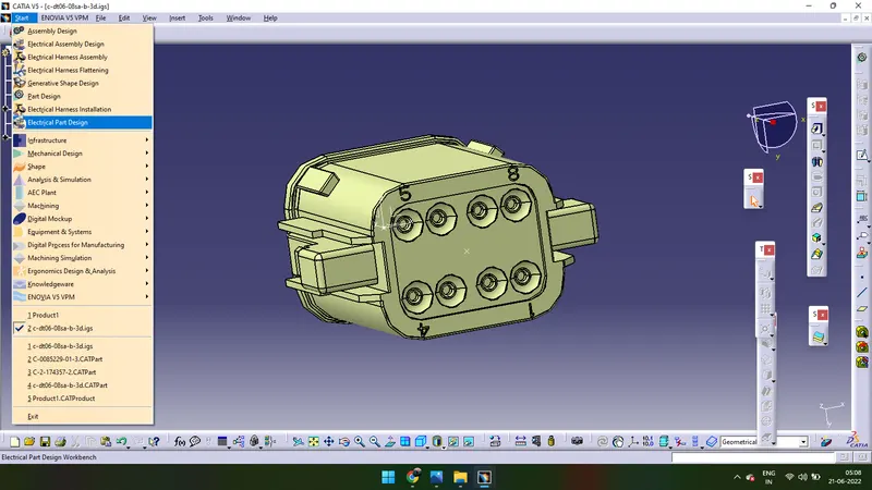
- Click on Start > Equipment & Systems > Electrical Harness Descipline > Electrical Part Design.
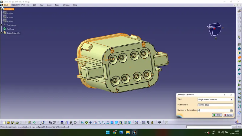
- Click on the Define Connector > Single insert connector > Enter ‘8’ in the Number of Terminations > Click on Ok.
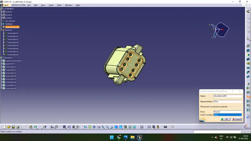
- Click on Bundle Connection Point > Click on the Connector > Representation will be the Face (click on the Face)> Point (click on the point) > Initial Condition will be the Face (click on the Face) > Click on Ok.
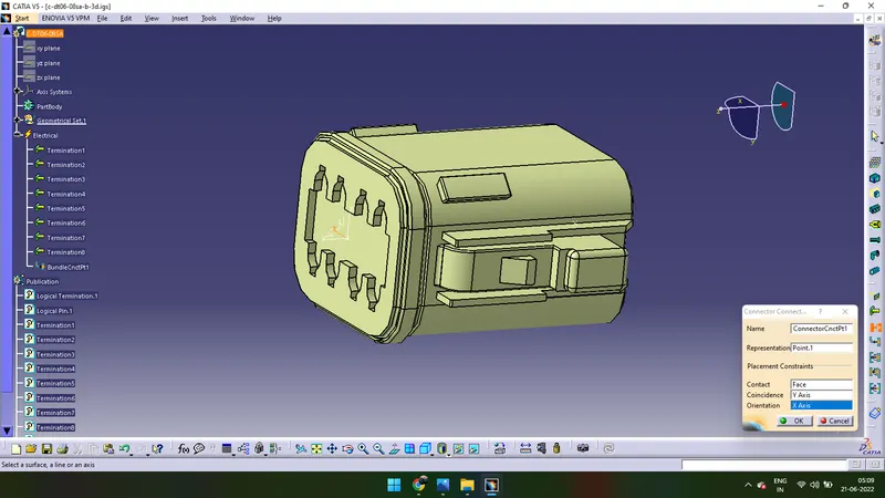
- Click on the Define Connector Connection Point > Click on the Connector > Representation will be Point (Click on the point) > Contact will bw Face (Click on theFace) > Coincidance will be Y-axis (Click on the Y-axis) > Orientation will be X-axis (Click on X-axis) > Click Ok.
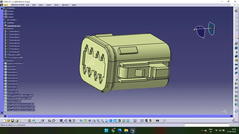
- Done (This is how we should define Connector).
2.Defining Second Connector with Cavity Connection to the Connector.
We have to downlWe oad the Connector 3D design from the link given above and we should extract the file. One is Connector 3D Design and another is Cavity 3D Design
We have to follow Steps which are mentioned in the above connector.
- Open the CATIA V5 click on file > open > click on the Extracted file. The CAD Design is appered on the screen
- Go to Start > Mechanical Design > Part Design.
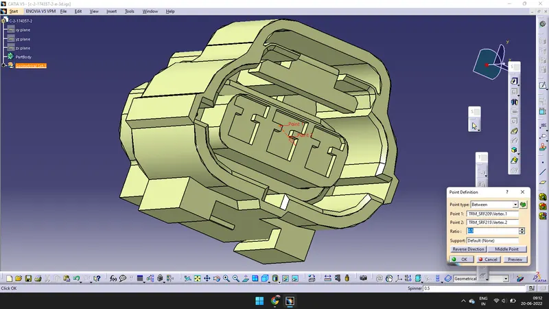
- Click on the Pointer Tool > click on Between > create two points and clink on Middle point > Ok. A point is created on connector side.
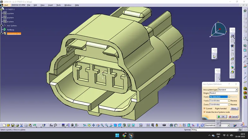
- After creating a point we need to create a axis by using aixs tool. If the x-axis is not in the direction of locking mechanism. Right click > Rotation > Type 90. it rotates 90 degrees.
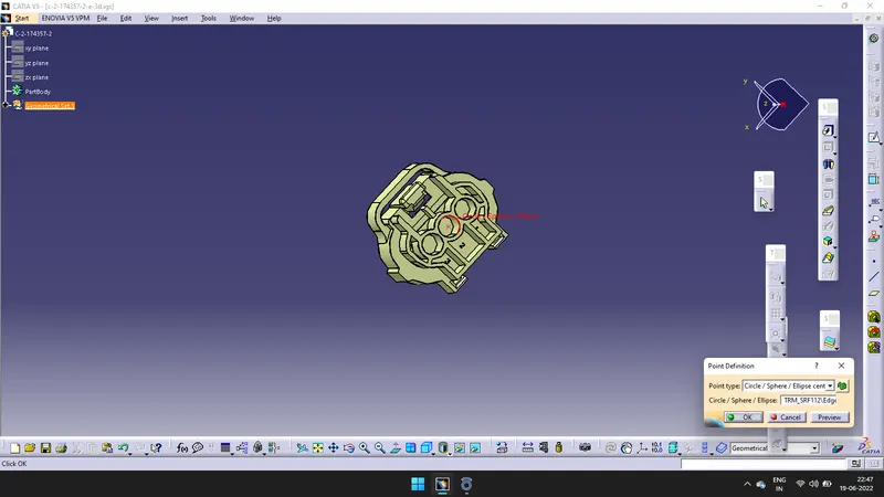
- Create a point on the bundle connection side by using pointer tool > Circle/shpere/ellipse option.
- Create another point on the base of the connector it is called as Cavity connection point. So create a point at the middle using the pointer tool > Between .
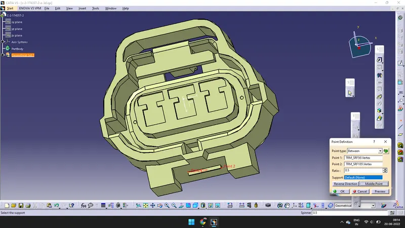
- After creating the point we have to create a axis by using aixs tool.
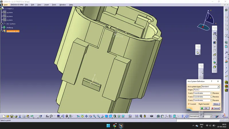
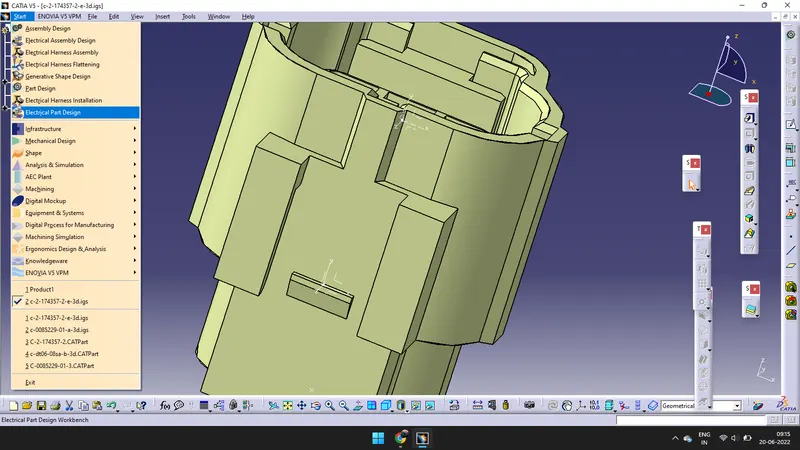
- GO to Start and click on Electrical part design
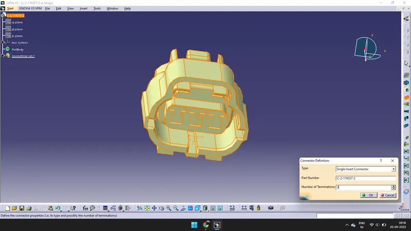
- Define the CAD design into Electrical component we need to use Define connector Tool. Number of Terminials are 3, we have to enter 3 and the type is Single insert connector.
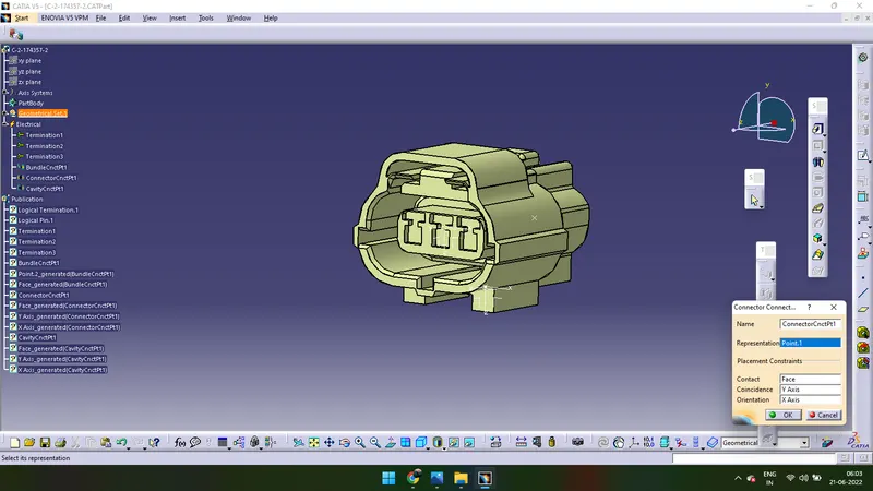
- We have to define the Connector connecting point bye using Define connector connecting point tool. Representation will be 'Point-1', Contact will be 'Face', Coincidence will be 'Y-axis' and Orientation will be 'X-axis'.
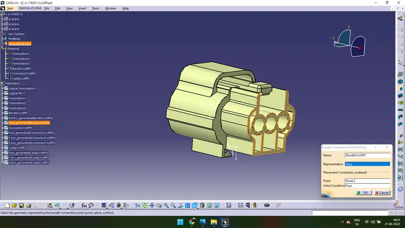
- We have to define the Bundle connecting point bye using Define Bundle connecting point tool.Representation will be 'Face'. Point will be 'Point-2' and Initial Conditions will be 'Face'.
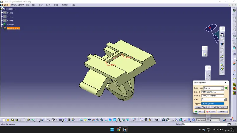
- Go to file and open the Cavity part and open Part design > Point tool > Between. Create a point and give the axis to the point by using axis tool.
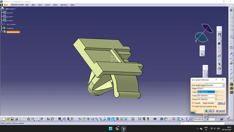
- Go to Electrical Part Design > Define cavity > click ok > Click on Cavity connection point and Representation will be 'Point-1', Contact will bw 'Face', Coincidenace will be 'Y-axis' and Orientation will be 'X-aixs'.
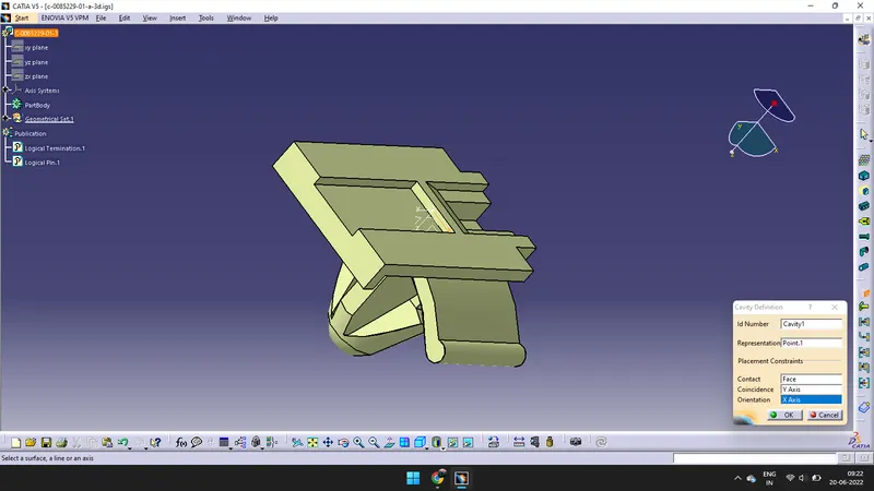
- Go to Start > Mechanical Design > Assemble Design > Click on Window > Click on previous Connector and Cavity Tabs and copy them and paste in the Assemble Design Tab on Product.
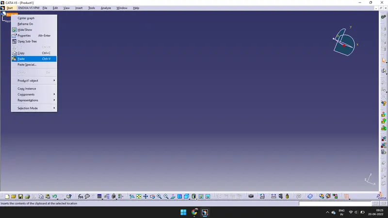
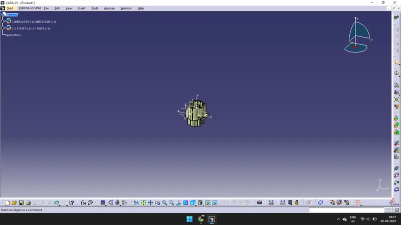
- Click on Manipulation > Move the cavity in X and Y direction, give correct orientation.
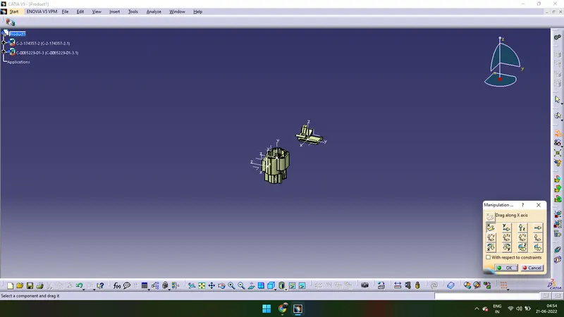
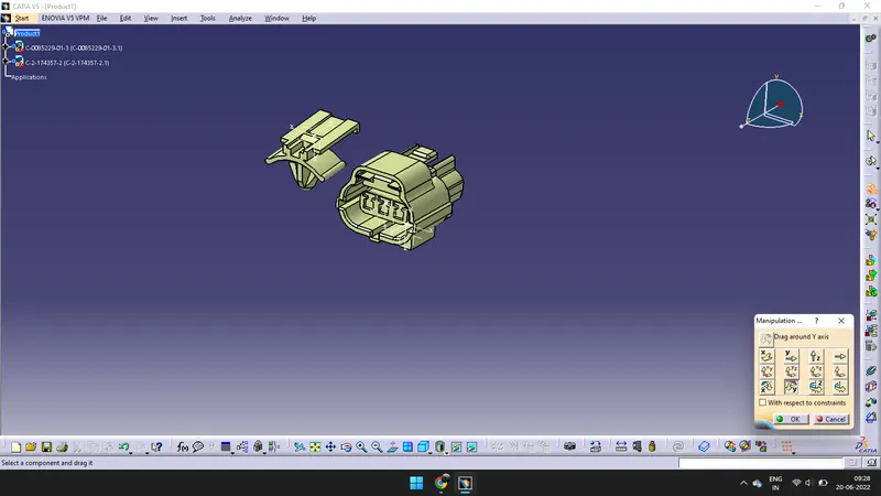
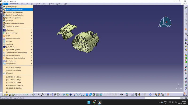
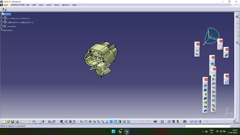
- After Manipulation > Click on Electrical Assemble Design > Click on Connect Electrical Devices > and Click on both Components. They get attached.
Electrical Distribution System
- Electrical Distributipon Sysytem basically deals with Physical & Logical Architecture, Schematic Development, Power distribution, Wiring harness Design, Wiring harness component Design of given Electrical system.
Connector
- Connector are responible to make contact between Wiring harness and components or between two different Wiring harnes assenbilis by offering mechanical locking and sealing to the joints