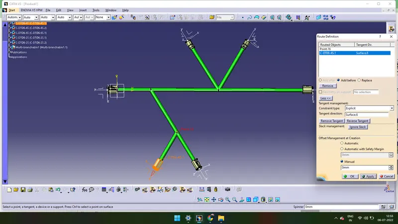
Wiring harness design in CATIA V5 - 3D modeling Week 4 Challenge
- We have to download all the CAD 3D design of connectors which are mentioned above.
- We have to convert the Mechanical CAD 3D design of connectors into Electrical component.
- We have to give Connector Connectiion Point and Bundle Connection Point to all the four connectors
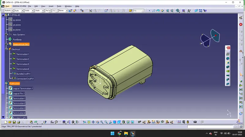
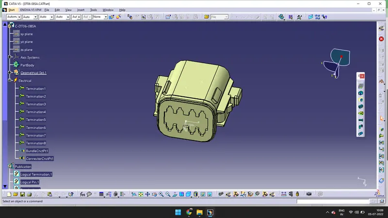
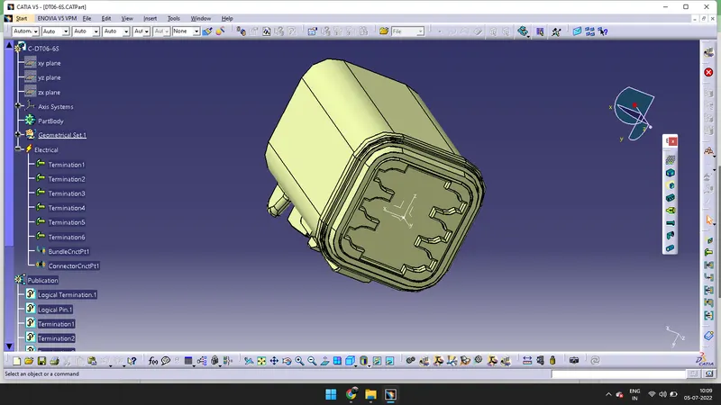
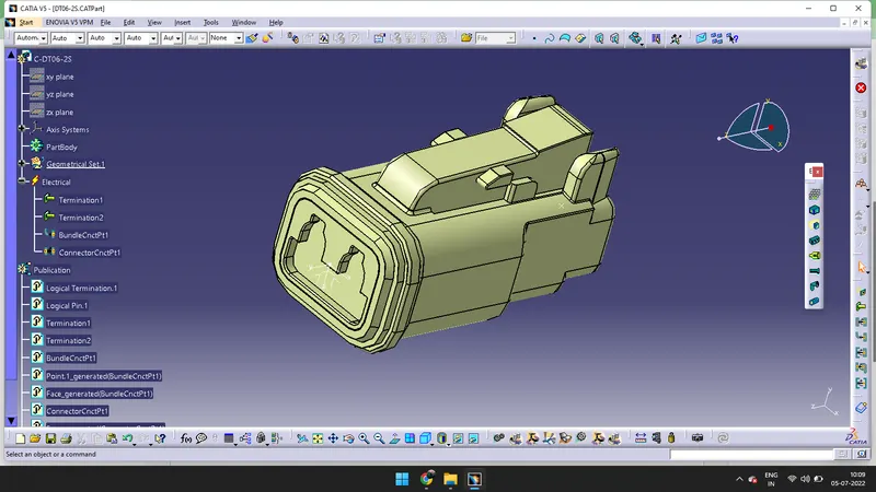
- According to my convenient, i created a sketch to avoid the confusion. We can also Manupilate without creating any sketch. We have create the sketch according to the dimensions given in the above figure.
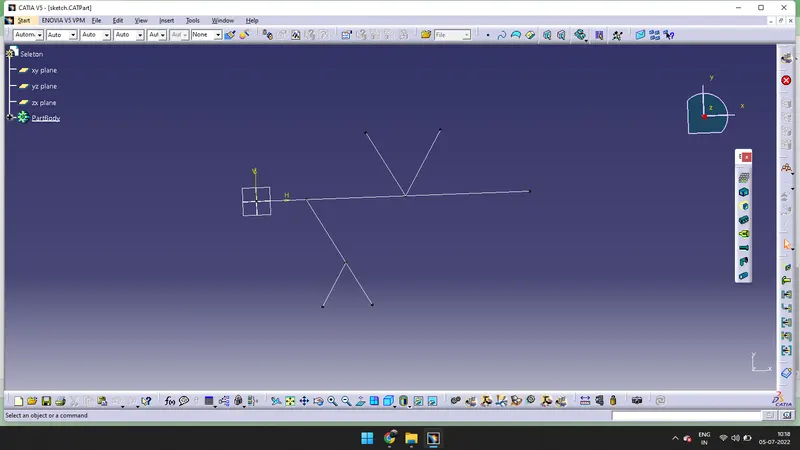
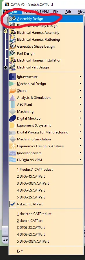
- Go to Start > Click on Assembly Design > Click on window > Open the Designs one by one copy them and paste it in the assembly design
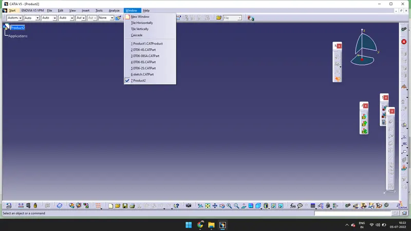
- After copying click on Product and past on it.
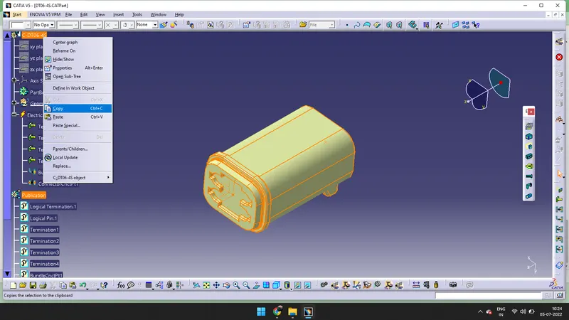
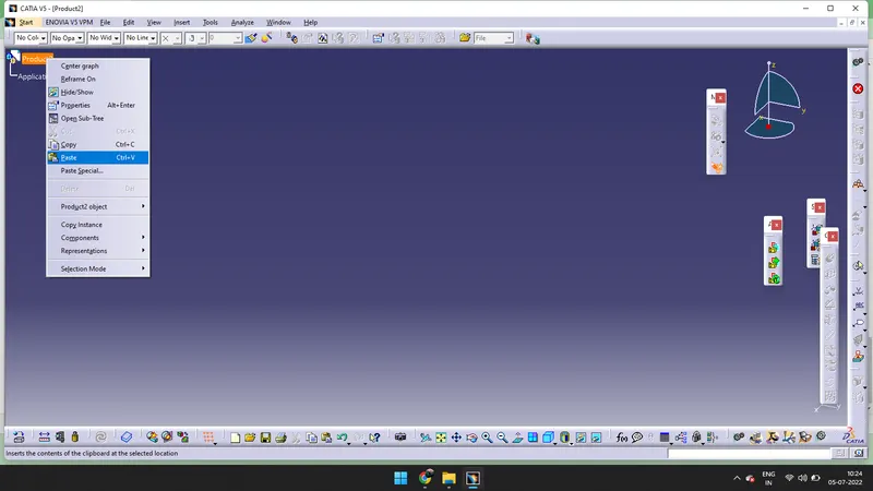
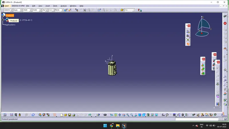
- Paste DT06-2S and 4S twice, paste DT06-08SA,DT06-6s and sketch one time.
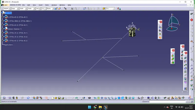
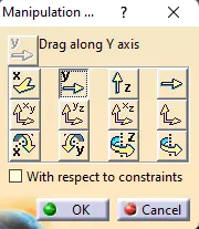
- Now we have to manipulate the connectors. Click on Manipulation > Select the direction(in which direction the connector can be placed). First option is the manipulation option, click on that.

-
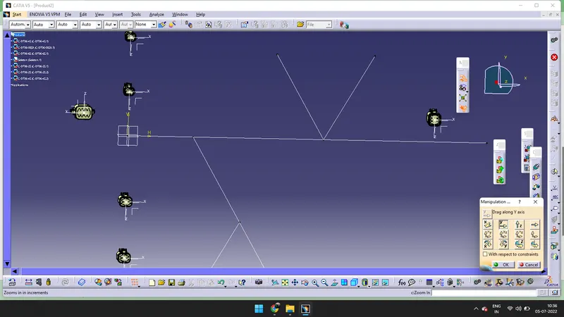
- Snap all the connectors according to the figure given above.

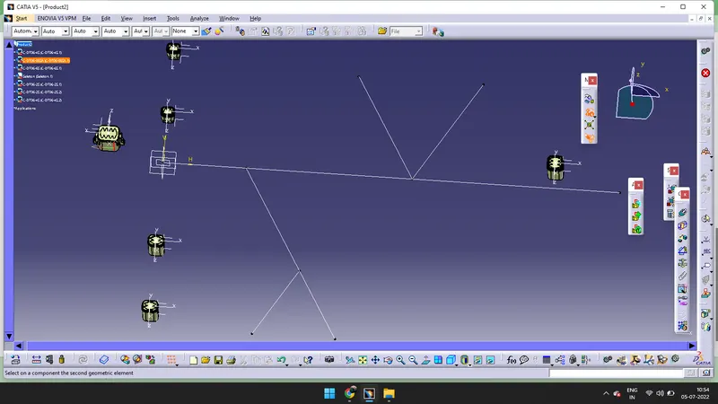
- Select the base on the connctor and select the line in wich wich direction we need to sanp it.
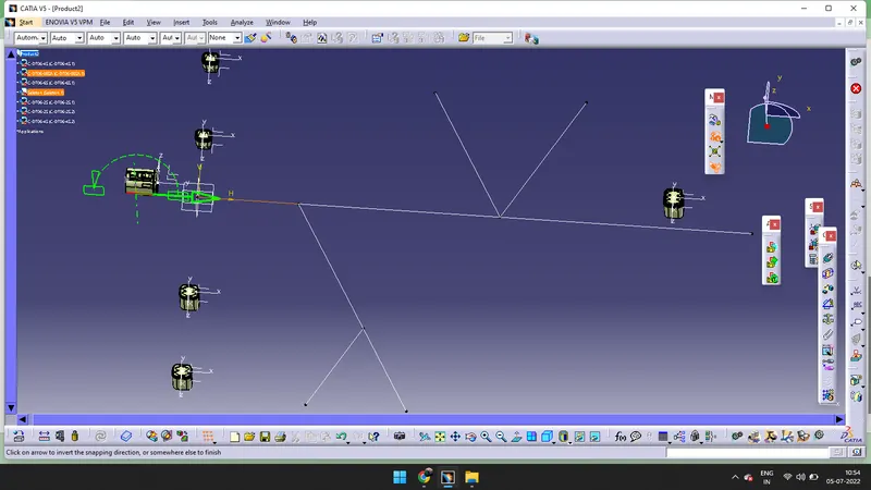
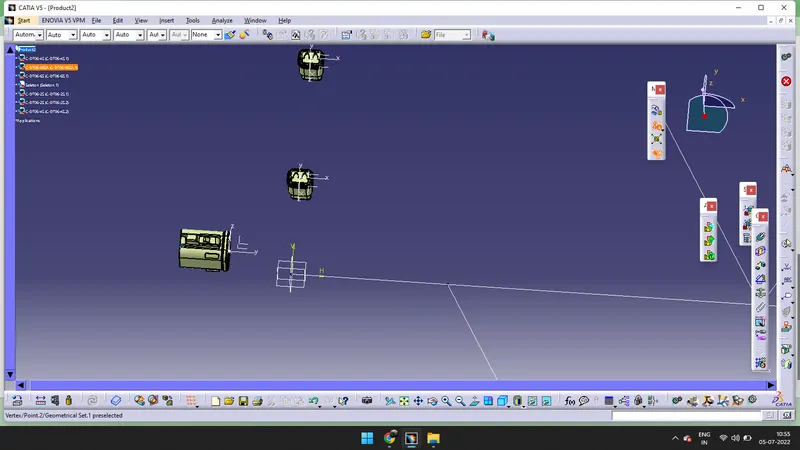
- By using compass we can rotate the object. Drag the compass and place it on the connectror, double click on the compass. We can see some options in that we need to rotate the connector in 180 degress. it will be rotated. After that click on snap > click on the connection connector point and click on the sketch point where the connector should be snapped.
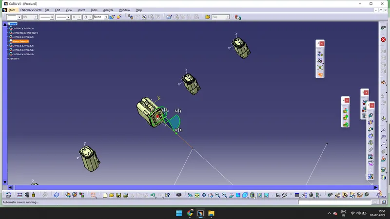
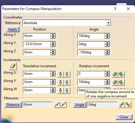
- Accordingly snap all the connectors and if the direction of the connector is wrong use compass and rotate it.
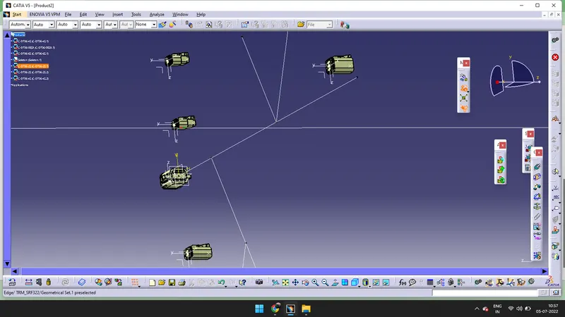
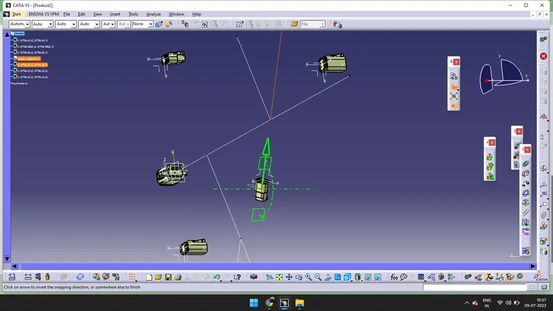
- All connectors are snapped and rotated acoordingly.
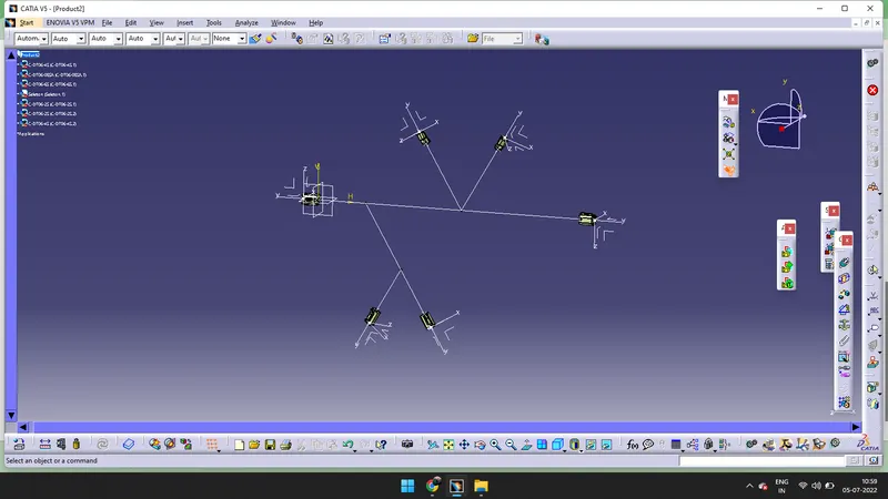
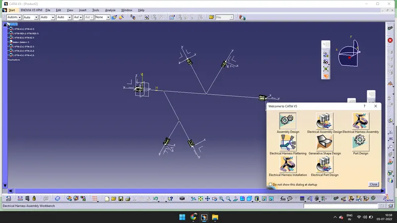
- Select the Electrical Harness Assembly
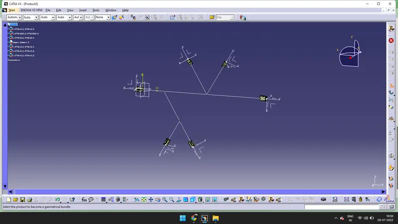
- Click on Geometrical bundle > Double click on the Product(it will be converted into electrically).
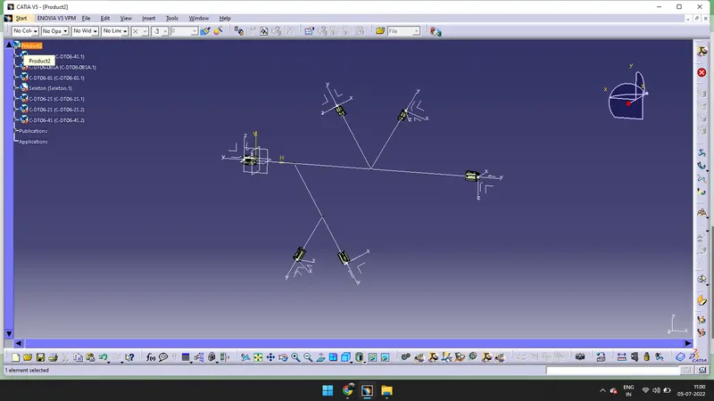
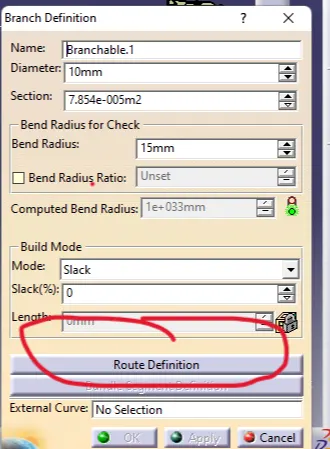
- Click on the Multi-brancable Document. > Go to Route Definition.
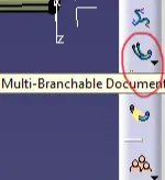 >
> 
- Click on the surface of the two connectors.
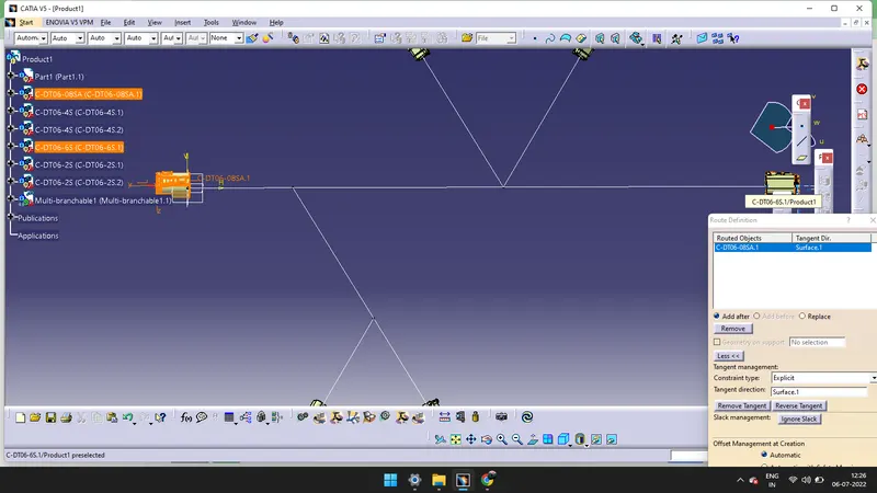
- It will be showing like this, We have to click on Reverse Tangent.
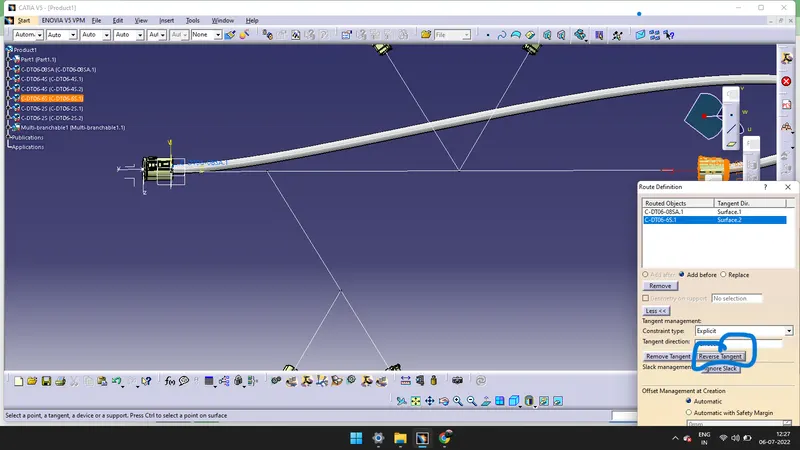
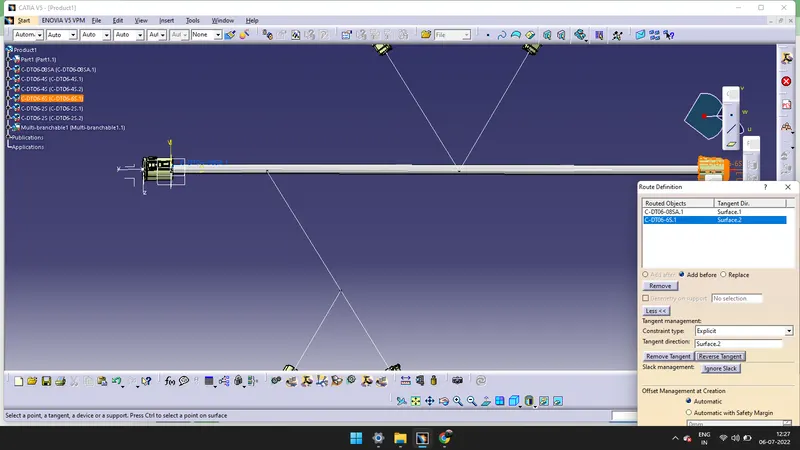
- Click on OK. The Branch is created.
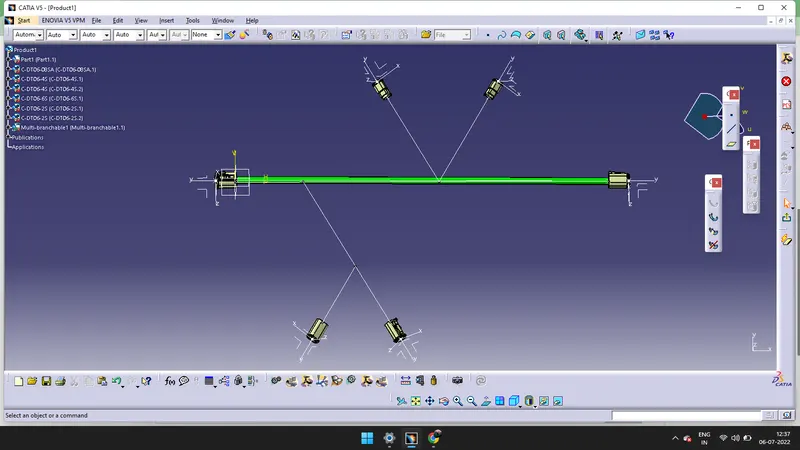
- We need to give branch point by using Add branch point command.

- Creat two points by selecting Add branch point command.
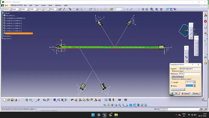
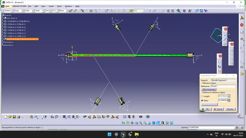
- After that click on Branch Definition > Go to Route Definition > Click on the point and on the connector.

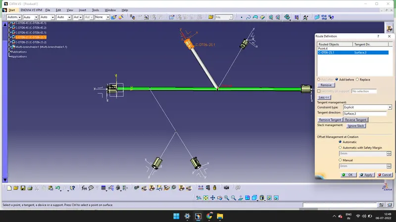
- If it is in different direction click on the Reverse Tangent option, it will be routed properly.
- Apply same step to another connector to create the branch.
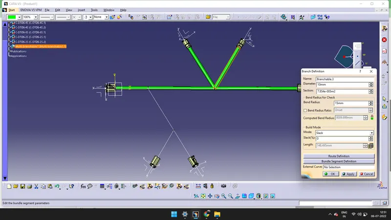
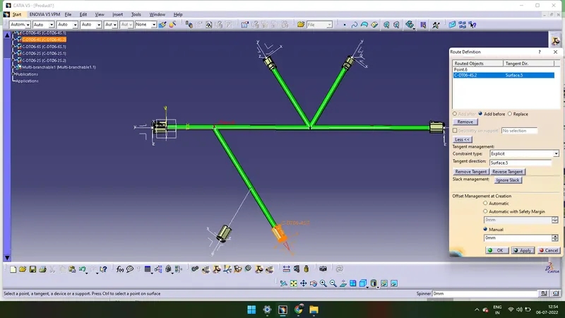
- Again we need to give the branch point by using Add branch point and create a branch by using same steps.