Wiring harness design in CATIA V5 - 3D modeling Week 2 Challenge
1)AIM :
Download following connectors & Connector clip cad data from given link & define it as Electrical Connector using Electrical Part design Workbench. Define all the necessary properties to Connectors & Clip.
OBJECTIVE :
To download the download the connectors and connector clip from the te.com website and import them to catia v5 software and define them as electrical component and give the necessary electical properties to them.
STEPS :
1)Download the cad files from the te.com website and import them to the catia V5 software.
2)Create the required geomentric parameters like points and axis
3)Define part as connector.
4)Define bundle connection point.
5)Define connector connection point.
6)Define cavity connection point.
GIVEN CONNECTORS :
1)Deutsch DT06 – 08SA
2)Tyco 174357-2
3)Tyco 85229-1
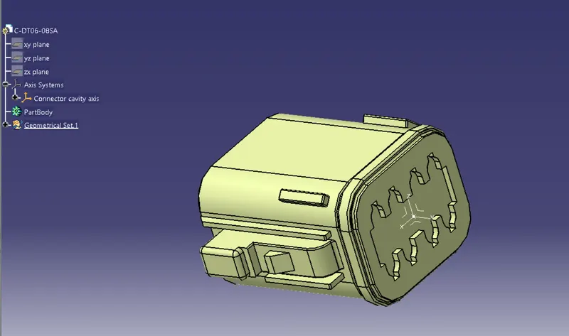
Deutsch DT06 – 08SA :
STEPS :
1)Initially the cad model was downloaded and imported from the te website.
2)Then the geometric parameter was set.
3)The point reference command was selected and placed in the middle of the mating side.
4)Then the axis point command was selected and was oriented in such a way that y axis points to direction of the mating side.Thus the connetor connection point was defined.
5)The electrical part design workbench was opened and the connector was defined as the electrical part.
6)Then the bundle entry point was selected and the number of termination points were given.
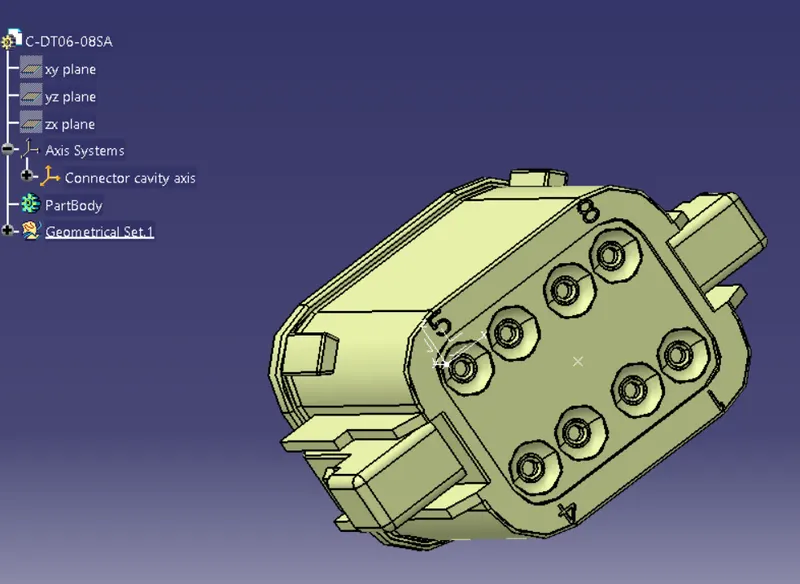
7)All the geometric parameters were done in the part design work bench.
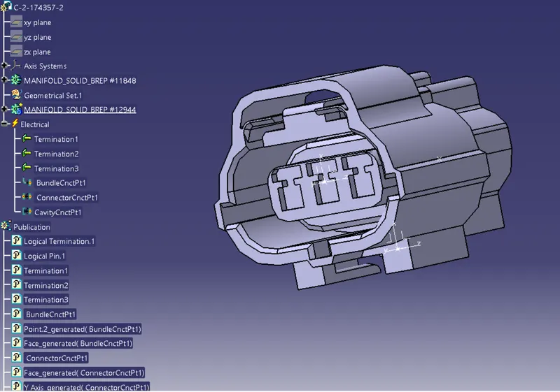
Tyco 174357-2
STEPS :
1)Initially the cad model was downloaded and imported from the te website.
2)Then the geometric parameter was set.
3)The point reference command was selected and placed in the middle of the mating side.
4)Then the axis point command was selected and was oriented in such a way that y axis points to direction of the mating side.Thus the connetor connection point was defined.
5)The electrical part design workbench was opened and the connector was defined as the electrical part.
6)Then the bundle entry point was selected and the number of termination points were given.
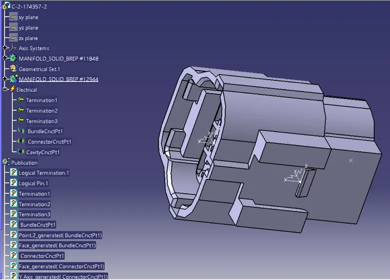
7)All the geometric parameters were done in the part design work bench.
8)Then the point and the axis was fixed for the cavity point.
9)The cavity connection point was fixed.
Tyco 85229-1 :
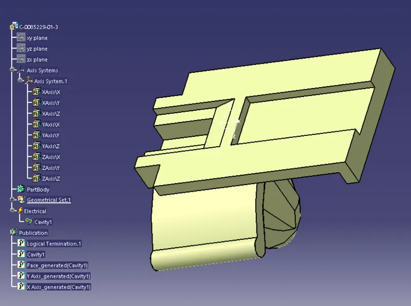
STEPS :
1)The cad file was downloaded and imported from the te website.
2)The point and the axis was defined.
3)The electrical part design workbench was opened and the cavity was defined.
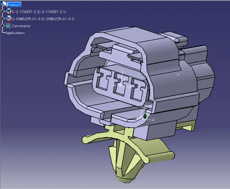
4)Then the assembly workbench was opened and both the connector and the clip was connected using connect electrical device command.
CONCLUSION :
Both the connectors and the clip were defined as an electrical connector and electrical mounting equipment respectively. All the necessary electrical and geometrical properties were given to the parts.