Wiring harness design in CATIA V5 - 3D modeling Week 2 Challenge
1, Initialy downloaded the connetors and mounting clip from te.com from the given links above and open in Part design work bench.
After that for define the connetors and mounting clips for Electricaly.
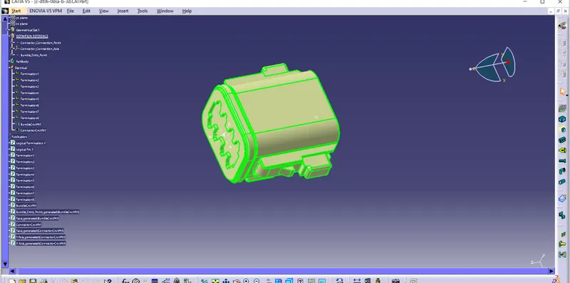
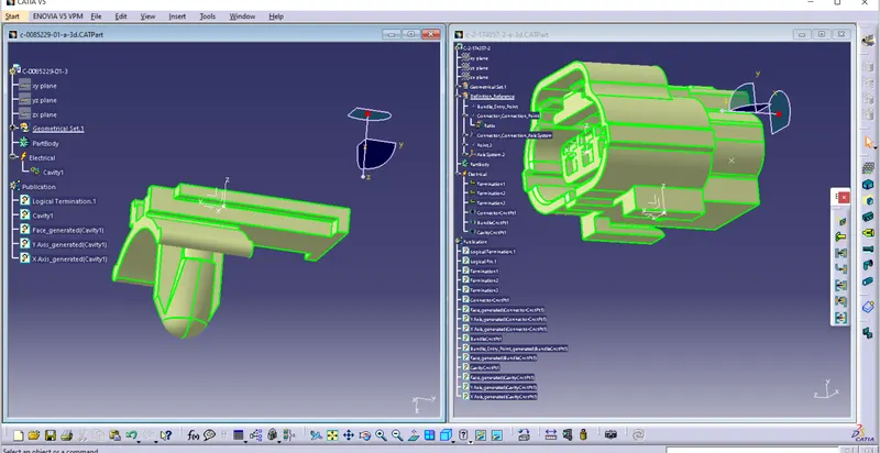
DT06-08SA Connector :- First identify the bundle connection port and connector connetion port virtually and created connector connection point and bundel connetion point at respective port of the connector in Part design workbench. After that creat axis system at Connector connection pint in such a way that the Y axis of the axis system is placed in parllel to the direction of the connector moving and X axis of the axis system is placed in the locking clip direction of the connector and Z axis is placed normal to the connector final face
For define the connector electricaly switch to Electtrical Part design work bench. Then using the tool called Define Connector. Click on that tool and after select the connector by click on connector and give the necessary datas like number of terminals and Name of the connector after that we can see some publications of the terminals on right side. Then define the bundle connetion point and Connector connection point by using tool Bundle connetion tool and Define connector connetion tool respctively.
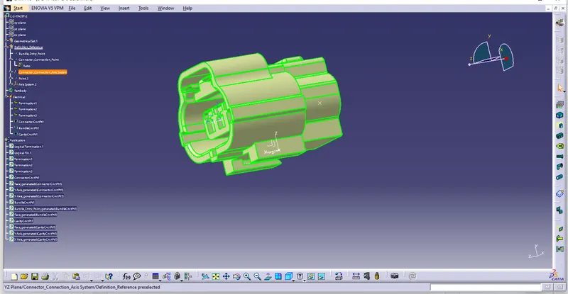
Tyco 174357-2 :- For define the part as an electrical all the steps are same as we done in DT06-08SA but aditionaly we need to locate Cavity connector Axis system for conneting the Mounting clip. So that created a point on the locking portion provided at cavity of the connector. Then Cavity axis system added.
Mounting Clip
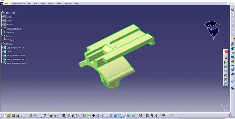
TYCO 85229-1:- inthis case we nned noly define as a support block by using tool called Define support block. so befor that define the part as a mounting equipment, for that simply click on tool called Define Mounting Equipment and give the necessery inputs and click ok after that define the part as a Mounting clip by click on Define Support Block tool . for that need point and axis on the clip so that located the point at the face that going to contact with the connector. after that locate the axis system on the point and arange all the axis of the axis system same as we provided on the connector cavity Axis system.
Catlogue :-
Created new catlogue by File -> New -> Catlogue Document and click on Ok and in the new window select family tool and give the name for the catlogue we going to creat and select Type as Electrical here i created for connector.
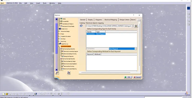
After that for guide the catlogue made some changes in the setings for that click on Tools -> Options -> Equipment & System -> select Electrical maping and slecte the family and define the objects maping and click on Ok.