Wiring harness design in CATIA V5 - 3D modeling Week 2 Challenge
WIRING HARNESS DESIGN
( Defenition of connectors and clips)
AIM:
The main objective is to define the given input as Electrical Device by using Electrical part design wokrbench and all th necessary properties of connectors and clip to be defined.
INPUTS:
Deutsh Dt06 - 08SA
Tyco 174357 - 2
Tyco 85229 -1
These are the products which are going to be defined as connectors and cavity based on its type. got these from Tyco Electronics.
| THEORY: |
wiring Harness
A wire harness, often referred to as a cable harness or wiring assembly, is a systematic and integrated arrangement of cables within an insulated material. The purpose of the assembly is to transmit signal or electrical power. Cables are bound together with straps, cable ties, cable lacing, sleeves, electrical tape, conduit, or a combination thereof. The wire harness simplifies the connection to larger components by integrating the wiring into a single unit for “drop-in” installation.
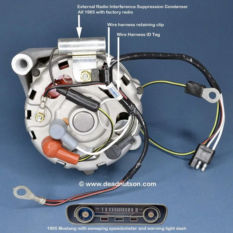 -> Example of Wiring Harness
- Connectors.
- Terminals.
- locks.
- Wires.
- cables.
- Protective coverings.
CONNECTOR
Connectors are the electro-mechanical devices used to form a continuous electronic signal to connect wire harnesses to a power source or circuit. On a basic level, connectors consist of male-ended plugs and female-ended jacks that can be joined together to relay an electronic signal. They are the familiar mating pair of polarized multi-pin connectors with wire leads. A male-ended plastic housing with release fits into a snap-mounted female-ended chassis mounting. The pair can be connected or disconnected easily and come in a variety of sizes, shapes, materials, quality, and dimensions—circular, header, pin, crimped, multitap—which are dependent on the application.
CAVITY CLIP
It's a type of clips which is used mate or attach the desired connectors or other electrical devices with supporting structure such as chassis, roof, pillars and other areas which has cavity to accomodate. It's a Plastic molded component and act as a Mounting Element
PROCEDURES
|
1. Create 3D object/Get from vendor |
| 2. Define Geomentrical parameters |
| 3. Define the 3d object as a connector |
|
4. Define connection points |
All the required 3D objects are either created or received from OEM. Here, all the products are downloaded from Tyco Electronics (TE).
Geometrical Parameters:
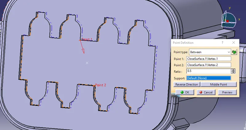
One of the most important factors to define electrical components. Mating between two components are defined by geometrical parameters such as points, planes and Axis. They are used to position the electrical equipments.
This has to be done on mechanical part design.
| Deutsh Dt06 - 08SA | Tyco 174357 - 2 |
 |
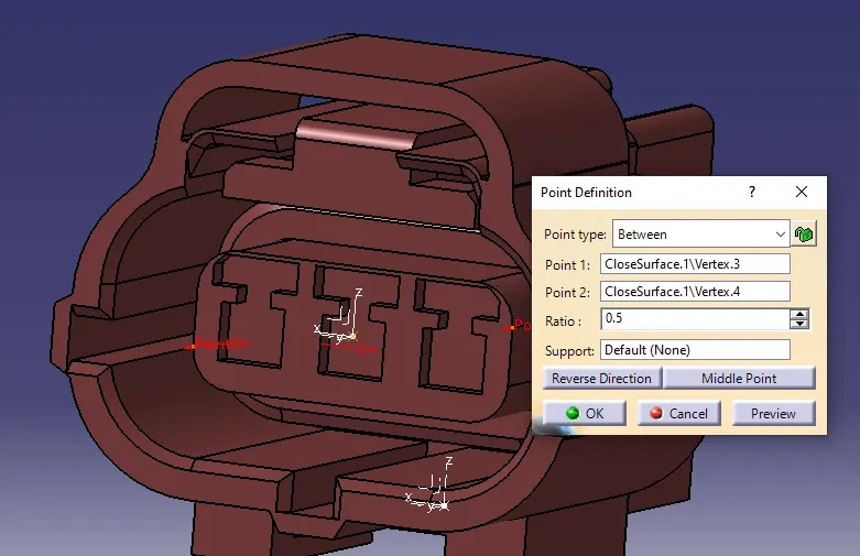 |
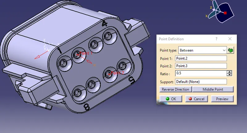
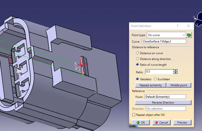
The above image shows creation of point at centtre of product to define connector connection point.
 |
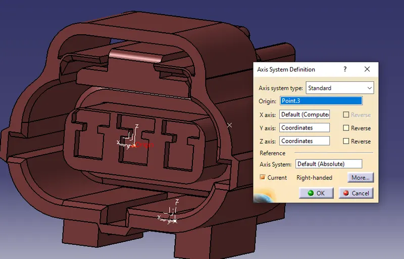 |
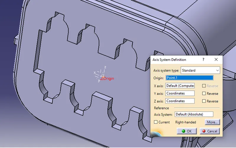
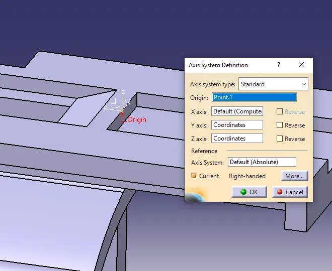
The above images shows creation of axis on the centre point of the product.
conditions - Y axis should be in the mating direction
x axis should be in the locking mechanism direction
z axis should be in the direction towards top surface
 |
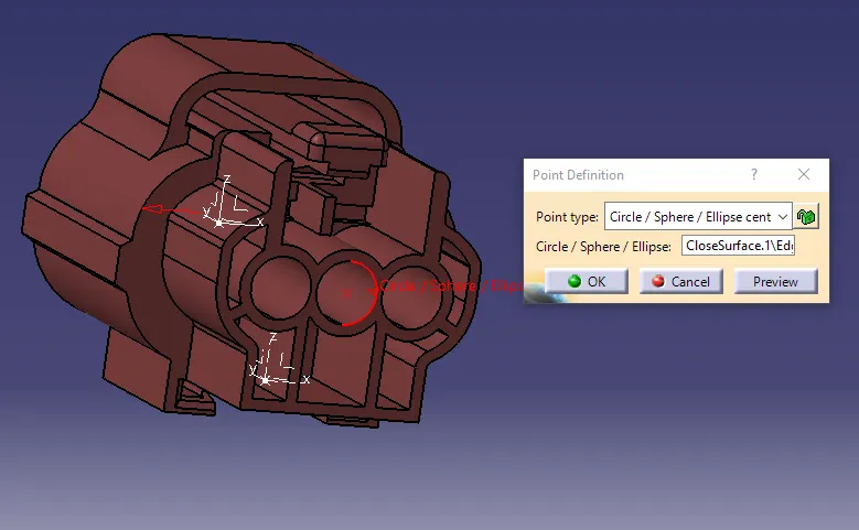 |
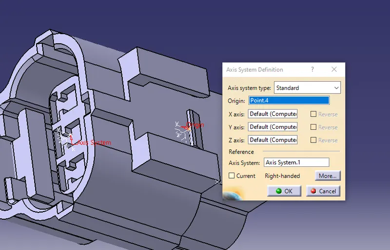
This is the other side of connector used to defining bundle connection point.
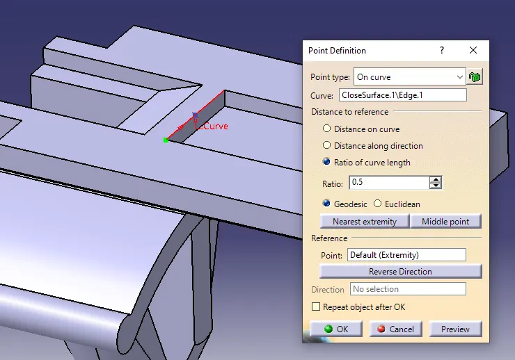
Geomentrical parameters for cavity clip and connector connection
| Tyco 85229 -1 | Tyco 174357 - 2 |
 |
 |
 |
 |
CONNECTOR DEFENITION
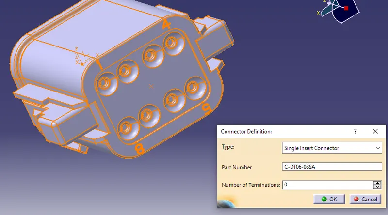
The given 3D object or part should be defined as connector. As an electircal equipment the electrical part design workbench could be used to do the required functions such as connector defenition, connector point defenition, Cavity point defenition and bundle point defenition.
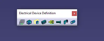 -> this is the tool bar to define the desired objects
To create connection points we should have a electrical equipment like connectors, we should define the part or 3d object as electrical device.
 |
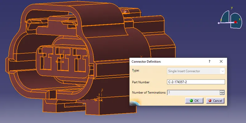 |
The above image shows how the part was defined as connector.
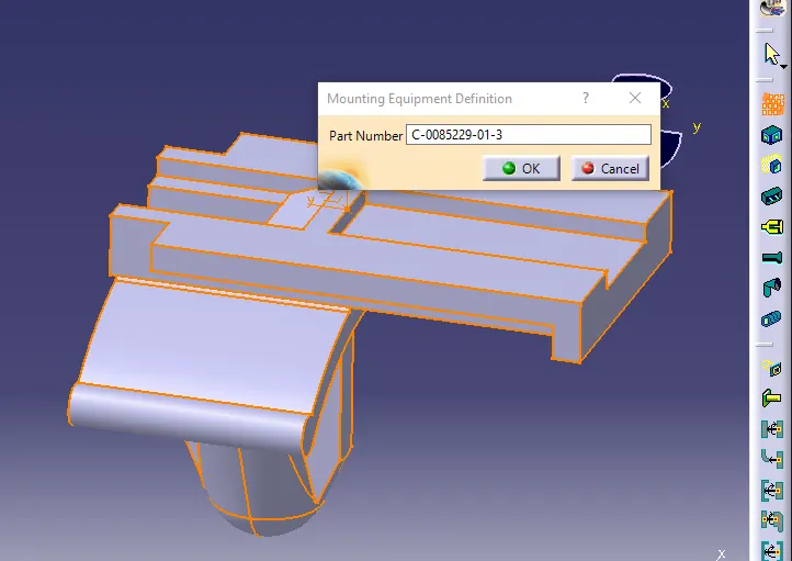 -> Mounting Equipment Defenition
Electical Connection Point defenition Toolbar
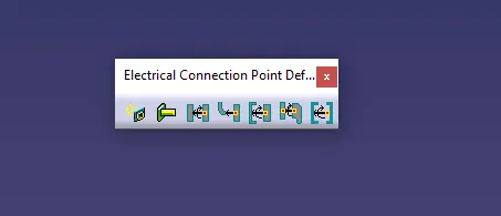 -> this is the toolbar in electrical part design to define connecting points.
Bundle Connection point
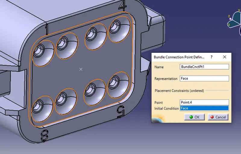
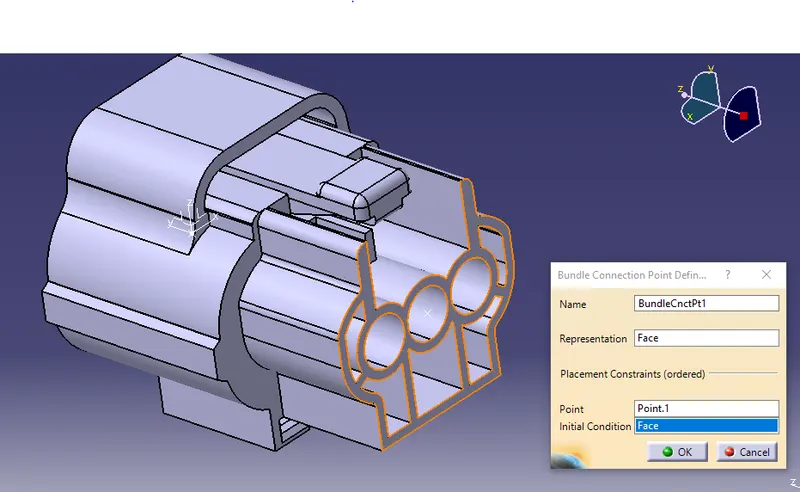
This is the point where bundle segment or wire point end when get routed to a connector. This point is known as Bundle Connection Point. At the time of defining bundle connection point, the number of terminals and a face is also provided as an input data.
| Deutsh Dt06 - 08SA | Tyco 174357 - 2 |
 |
 |
Connector Connection point:
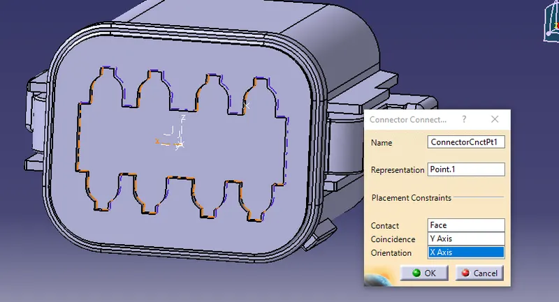
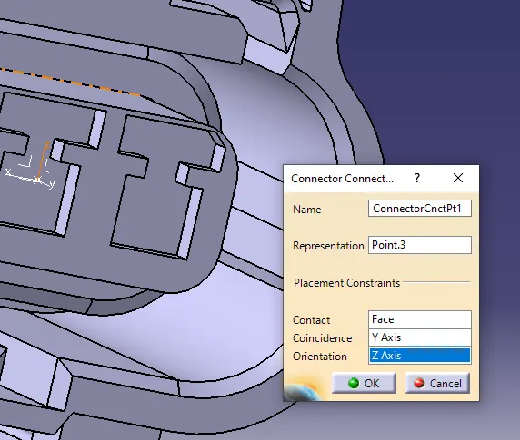
A connection point is a point in an electrical connector where a cable begins or ends. Electrical connectors are required to have at least one connection point with the route type set to Electrical. This defines the part as an electrical connector and provides information about the route
This point also used to make an assembly with other systems. This willl be defined by geomentrical parameters that we have already created.
- In Connector connection axis system, we have to always ensure that y-axis should be alwyas in the direction of mating axis of all the connectors.
- And x-axis should be in the diretion of locking mechanism and z-axis should be left-right side of the connector according to the orientation.
| Deutsh Dt06 - 08SA | Tyco 174357 - 2 |
 |
 |
Result
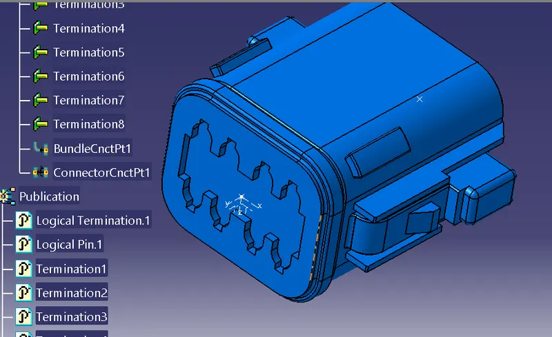
Deutsh Dt06 - 08SA
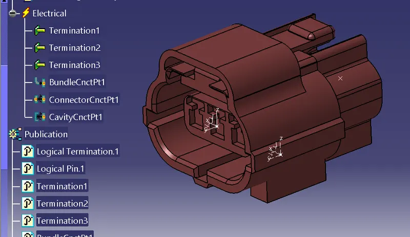
Tyco 174357 - 2
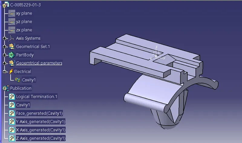
Tyco 85229 -1
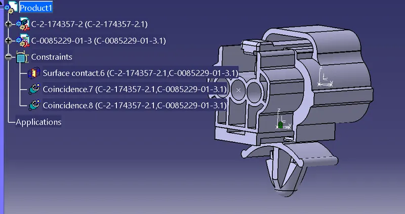
Assembly of cavity clip and connector
conslusion,
Thus all the given parts are defined as Electrical equipments and all the necessary Geomentrical properties of connectors and clips were defined successfully.