Wiring harness design in CATIA V5 - 3D modeling Week 2 Challenge
Connector :-
1. Deutsch DT06 – 08SA
process:
- Create midpoint on the contact face which will be normal to wire bunddle insertion.
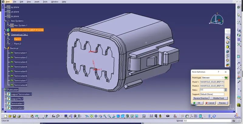
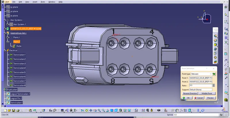
- Craete Axis System with respect to the point which we have created and defining the axis direction as shown below,
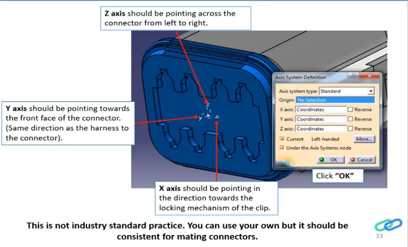
- In the Axis system X-axis rotated 90 degrees to make Y-Axis Coincidence for Assembly purposes.
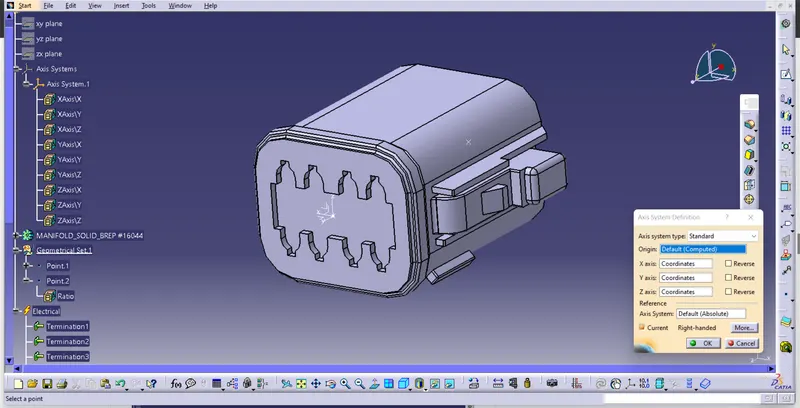
- Bundle connection point:
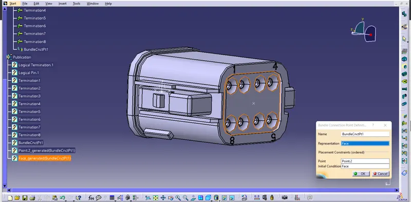
- Connector definition and bundle, connector connection points were performed in electrical design workbench
2.Tyco cunnector - 174357-2 :-
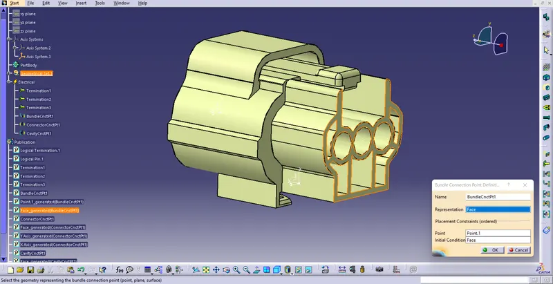
This is a female terminal which has both connector definition as well as a mounting slot by a clip.So in this model there should be a connection definition, connection, bundle point connections.Cavity definition and cavity connection points also must be given.
process:
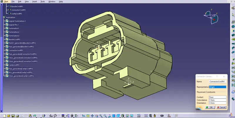
- create Connector connection axis system
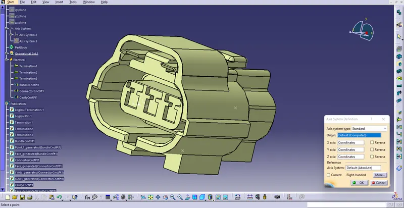
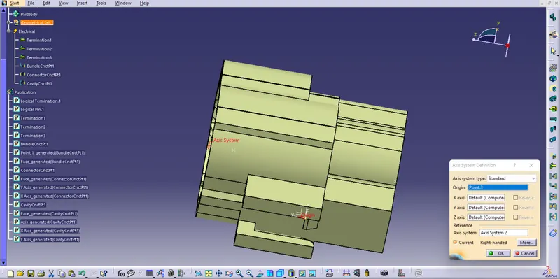
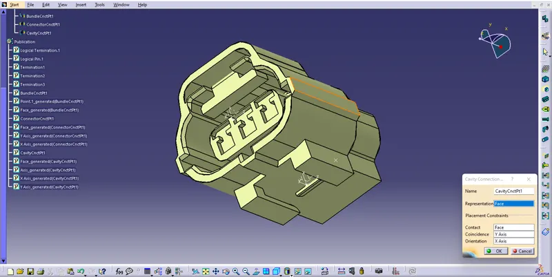
- The cavity connection side is defined as a Cavity connection point.
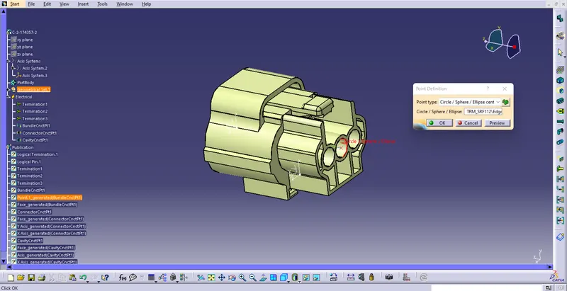
- Define Bundle connection point
- create cavity connection axis system
- Define Connector connection point and cavity connection point
3. Mounting Clip - Tyco 85229-1 :
First, I loaded the model from the given link.
process:
- create cavity connection axis system and orientation should be same as in connector
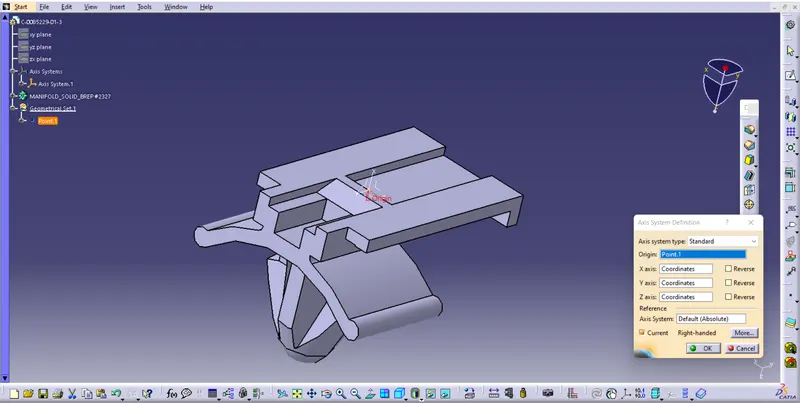
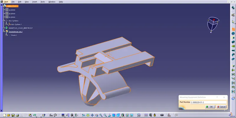
- Switch to Electric part design and define part as Mounting Equipment
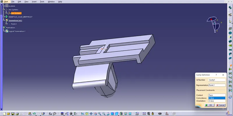
- Define cavity connection point
Elctric Assembly Design :-
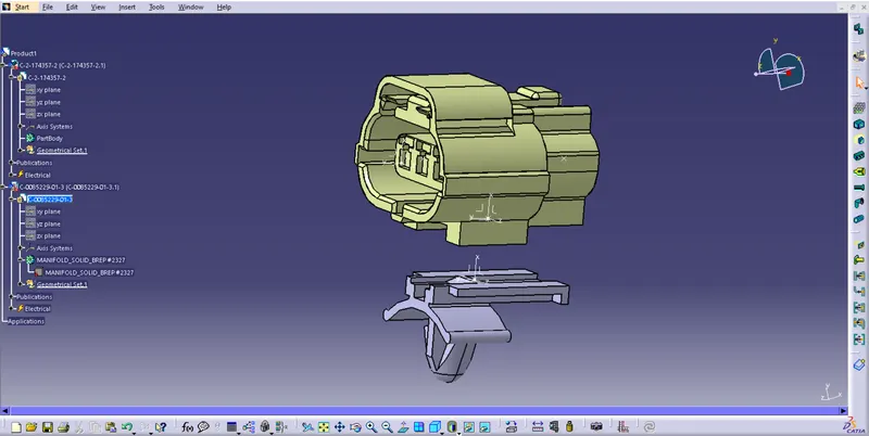
- Import Connector and cavity / mounting clip.
- Select Defing Eelectric connection
- select cavity and then connector.
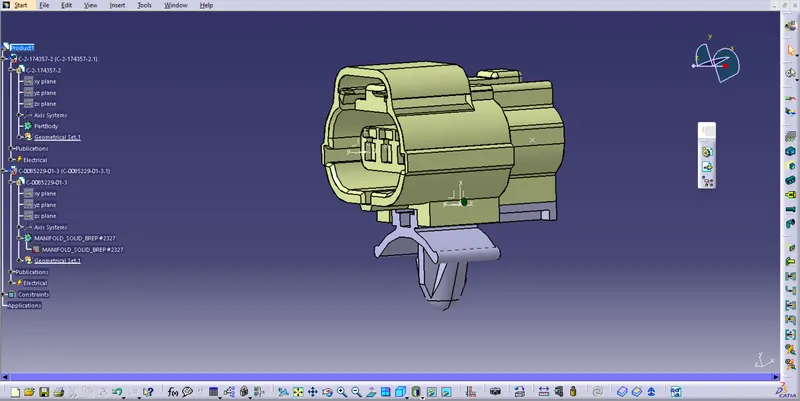
Then connect electrical devices connector 1 and mounting clip before that we need to do manipulation in Mechanical Design ->Assembly design.
Rotate the mounting clip along the x-direction to match the connector