Week 9- Unsteady moving zones Approach
- Unsteady moving zones approach.
- Aim - Simulate motion of blades using an unsteady approach of generic turbomachinery component.
- Objective - To Simulate the motion of blades in a generic turbomachinery component using an unsteady approach.
- Assume blade rotation at 300rpm
- Choose an appropriate time step for the simulation and generate an animation file for the rotation.
- Problem Specification
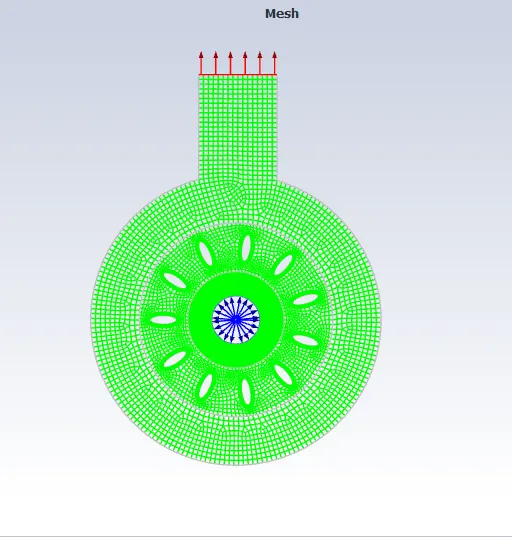
- Consider a generic turbomachinery component which consist of 10 blades.
- It has chord length of 0.6 m & spaced 36 degrees apart from each other.
- Blades are rotating at 250 rpm and flow is assumed to be turbulent.
- Simulate flow under no load conditions and inlet and outlet are at ambient conditions.
- Introduction
- MRF -Moving reference frame approach is a steady state method used in CFD to model problems with rotating parts.
- In MRF approach frame is moving and mesh topology remains same.
- There is no change in control volume.
- Independent mesh for each zone.
- Types of moving reference frame:
- Single moving reference frame.
- Multiple moving reference frame.
- Moving mesh approach.
- Moving mesh approach is used for modelling unsteady phenomena such as vortex induced flows, interaction of vortex with bodies.
- Computational mesh moves to simulate fluid/ solid objects in a domain.
- This approach requires time dependent solution.
- Sliding mesh method simulates fluid structure interaction problems such as flow around spinning machinery, oscillating structure and fluid elastic vibrations.
- Procedure
- Setup
- Import a given mesh file in fluent.
- Moving Reference frame approach - steady state simulation
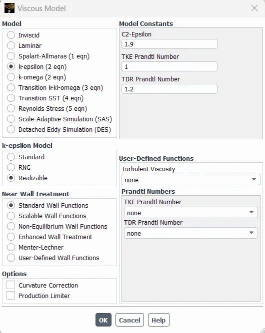
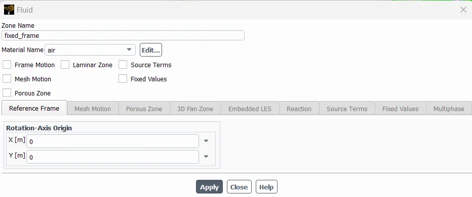
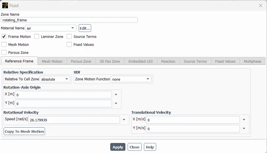
- Boundary conditions
- Inlet - Pressure inlet
- outlet - Pressure outlet
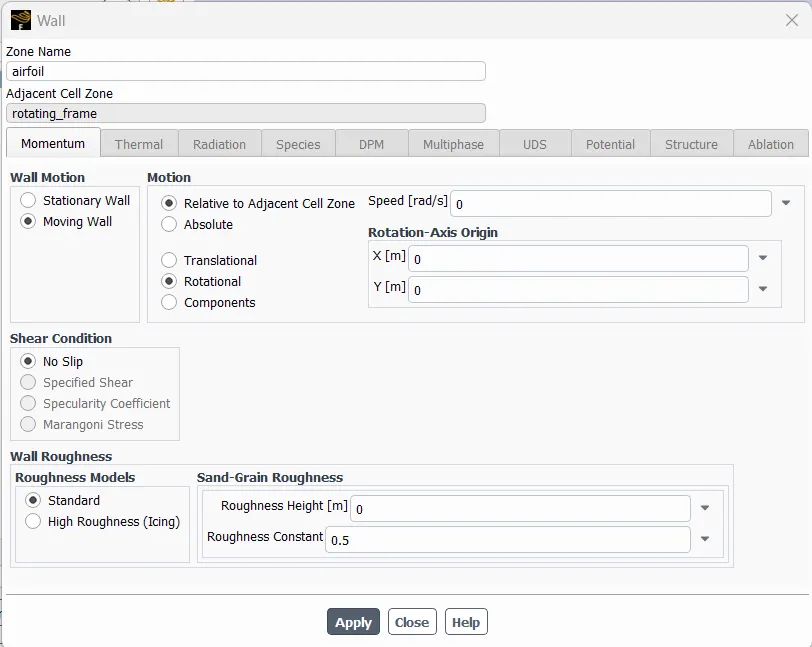
- Airfoil
- Results
- Static pressure contour
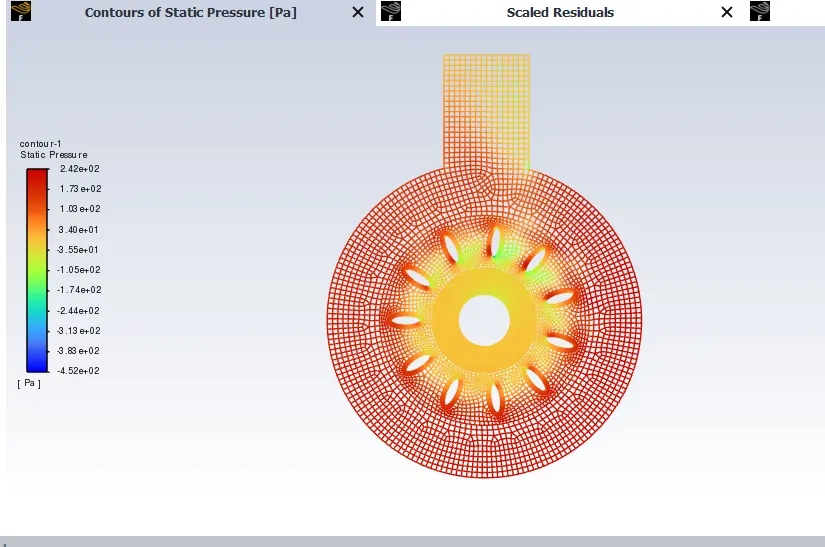
- From the above contour we observed that pressure is negative at the inlet and outlet part .Maximum pressure is generated at the leading edge of the airfoil and on the outer part of the domain.
- Total pressure contour
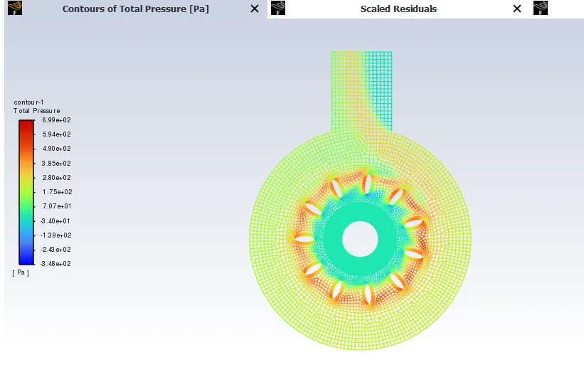
- From the above contour we observed that total pressure is maximum around the airfoil and minimum at the outer domain and some part of outlet section.
- Velocity Magnitude
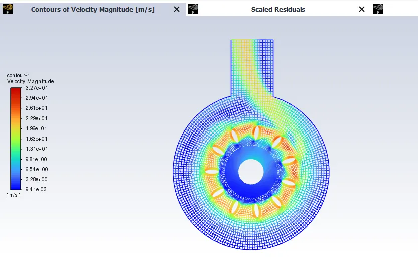
- From the above contour we observed that Minimum velocity (94.1m/s) is created at inlet part of the frame. Flow separation is observed at the rotating frame interface. Maximum velocity is created near the airfoil section.
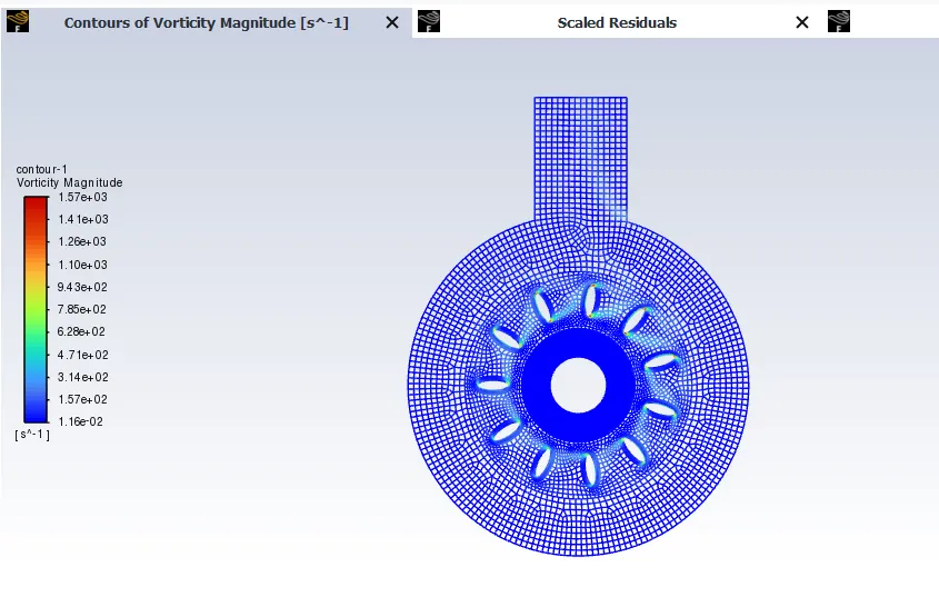
- Vorticity Contour
- Unsteady Case
- Run Transient simulation
- Assume blade rotation at 300rpm
- Moving mesh approach
- Cell zone conditions
- Boundary conditions
- Reference values
- Hybrid initialization
- Rotation of blade(N)= 300 Rpm
- To find the time period = T =60/N
- i.e Time required for one complete revolution (T) =0.2 sec
- So the Time step size=0.0002 sec
- Number of time steps = 1000
- Results
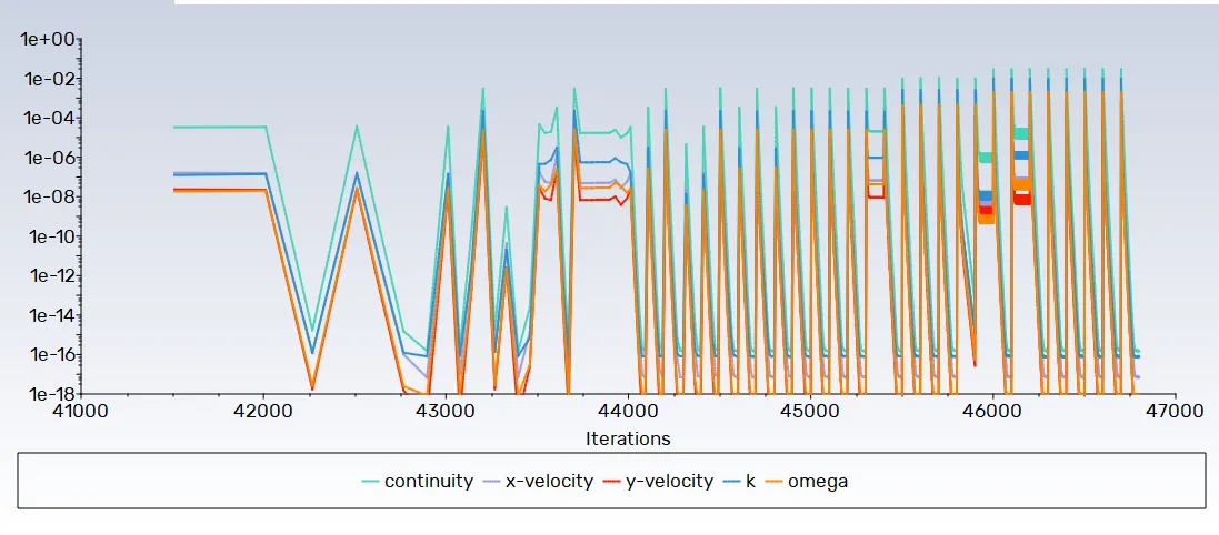
- Residual plot
- Velocity contour
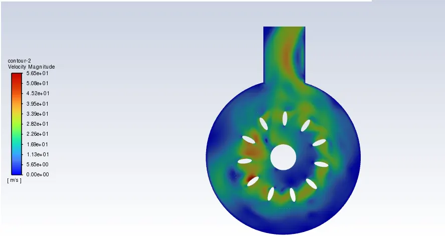
- From velocity contour, we can say that the velocity near the airfoil and at outlet region is maximum and at wall of the surface body and in some region of fixed frame the velocity is minimum.
- Static Pressure contour
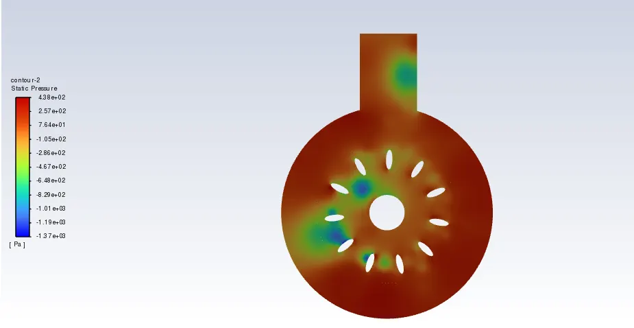
- In the above pressure contour we observed that maximum pressure is created on outer wall, near airfoil and some part of the outlet section. Negative pressure observed near the leading edge of the airfoil and at some part of the outlet section.
- Total pressure contour
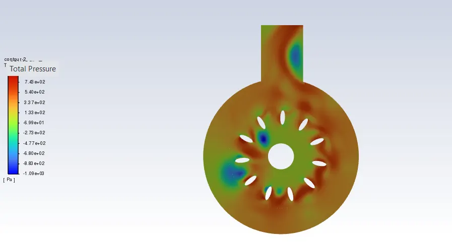
- From the above contour we observed that maximum pressure is observed near the airfoil and in some part of the outlet section. Maximum flow separation takes place due to negative pressure gradient.
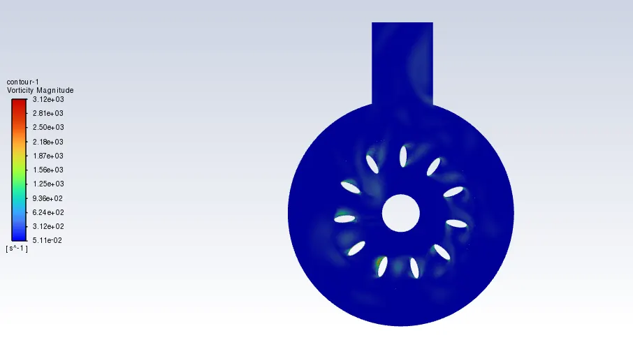
- Vorticity contour
- Velocity animation google drive link
https://drive.google.com/file/d/1hgRmgyUyH9-7imNjDj1PFQ1Kv4zad1O3/view?usp=drive_link
- Pressure animation google drive link
https://drive.google.com/file/d/1ADdEHbZJov_xzGyqLZvVuXBBBDxUfV_m/view?usp=drive_link
- Conclusion
- The simulation of the motion of blades in a generic turbomachinery component using an unsteady approach is done.
- Appropriate time step is calculated.
- Animation file for velocity and pressure is obtained.