Week 9 Tension and Torsion test challenge
OBJECTIVE
To perform the tension and torsion test simulation on the specimen by following the necessary boundary conditions,
- For the tension test, one end of the specimen has to be displaced to 18mmwhile keeping the other end fixed.
- For the torsion test, one end of the specimen has to be displaced through an angle of 1200 degrees while keeping the other end fixed.
To find out Total Deformation, Equivalent (v-m) Stress, Equivalent Elastic Strain and Temperature on the specimen for both tension and torsion tests.
- THEORY
1.1 Tension Test:
Tensile testing is a fundamental material science and engineering test in which a specimen is subjected to a controlled tension until failure. Properties that are directly-measured via a tensile test are ultimate tensile strength, breaking strength, maximum elongation and reduction in area. From these measurements, the following properties can also be determined: Young's modulus, Poisson's ratio, yield strength, and strain-hardening characteristics.

Fig.1.1 Tensile test specimen.
The preparation of test specimens depends on the purposes of testing and the governing test method or specification. A tensile specimen is usually a standardized sample cross-section. It has two shoulders and a gauge (section) in between. The shoulders are large so they can be readily gripped, whereas the gauge section has a smaller cross-section so that deformation and failure can occur in this area. Tensile tests are performed on universal testing machines.
1.2 Torsion Test:
Torsion testing is a type of mechanical testing that evaluates the properties of materials or devices while under stress from angular displacement. The most common mechanical properties measured by torsion testing are modulus of elasticity in shear, yield shear strength, ultimate shear strength, modulus of rupture in shear, and ductility.
Many products and components are subjected to torsional forces during their operation. Torsion testing is necessary when engineers wish to change or update the materials used in these products. Torsional testing can help the engineer identify an appropriate material that will possess the required torsional strength.
2. STEPS FOR PERFORMING ANALYSIS:
1. Open ANSYS workbench.
2. Select the static structural module.
3. Select the proper Engineering data card.
4. Import geometry.
5. Open Mechanical model.
6. Give proper connections (contacts and joints).
7. Generate mesh.
8. Set Analysis Setting as given.
9. Insert output request
10. Analyze Result.
3. ANALYSIS SETUP:
3.1 Geometry:
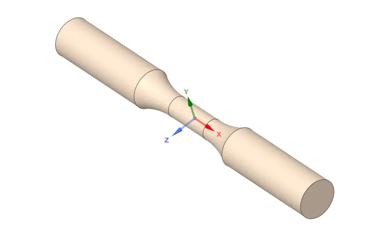
The given 3D model of tensile and torsion test specimen is imported into SpaceClaim.
3.2 Meshed Model:
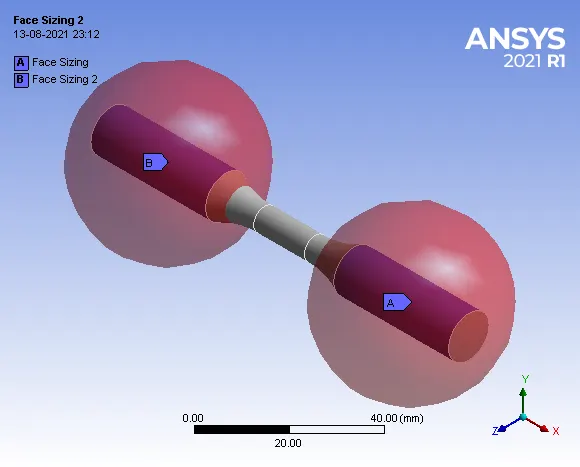
Fig. 3.2(a) Face sizing at gripping section (sphere of influence).
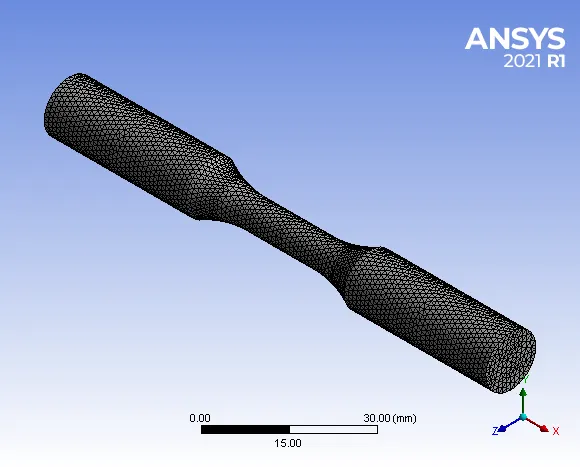
Fig 3.2(b) Meshed Model
- Details:
- Face Sizing(Sphere Of Influence) = 22 mm
- Patch Conforming Method = Tetrahedrons
- No of Nodes = 10442
- No of Elements = 49648
3.3 Boundary Conditions:
(3.3.1) ANALYSIS SETTINGS:
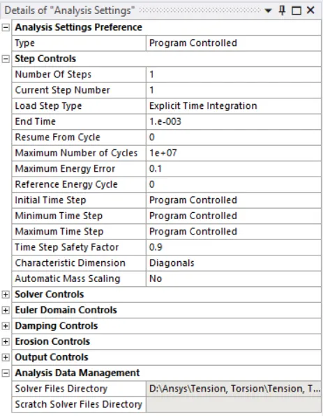
In the analysis settings, the number of steps considered is 1. The end time specified is 1e-003. The maximum no. of cycles is 1e+07. The maximum energy error is 0.1. The initial, minimum and maximum time step is set to ‘Program Controlled’.
(3.3.2) Other Boundary Conditions:
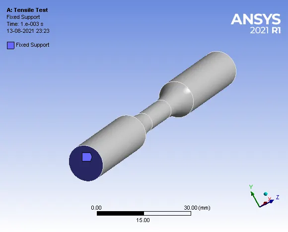
1. Fixed Support: Fixed support specified at one end of the specimen for both tensile and torsion tests.
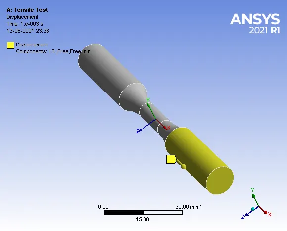
2. Displacement specified to the other end of the specimen for tensile test.
- Detail
- 18 mm in the X direction
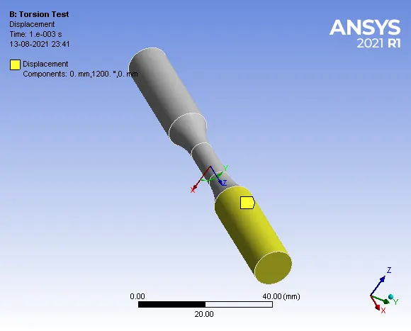
3. Displacement specified to the other end of the specimen for the torsional test.
- Detail
- First Create a new cylindrical coordinate system as shown in the figure.
- 1200 Degree in cylindrical Y-axis.
3.4 SOLUTION:
- After giving proper Boundary conditions, create a solution for the output result.
- Total deformation of the specimen.
- Equivalent stress of the specimen.
- The temperature of the specimen.
4. RESULT AND DISCUSSIONS:
(A) Tension Test:
1. Total Deformation:
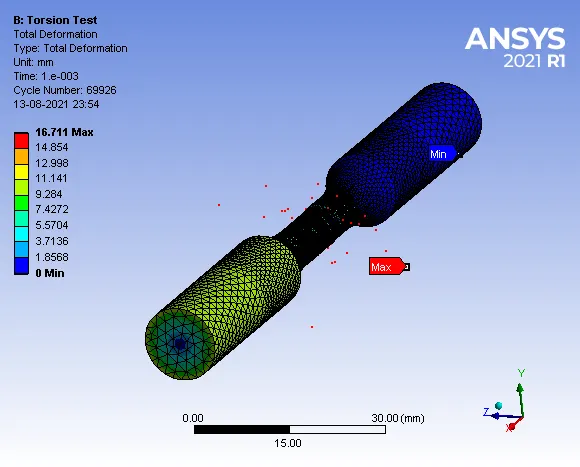
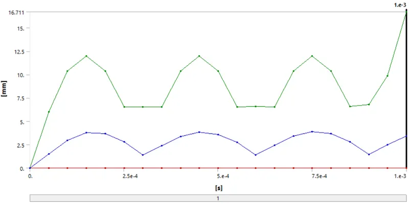
Maximum Deformation = 16.711 mm
- Deformation Contours:
2. Equivalent Stress:
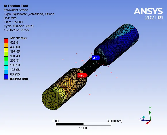
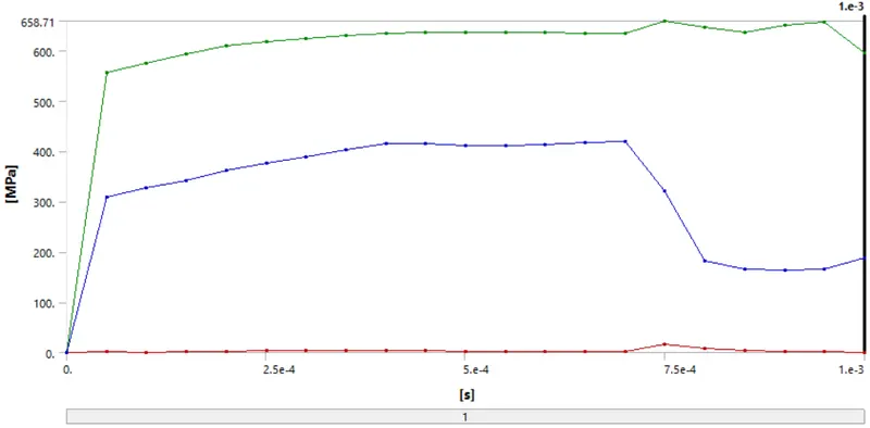
Maximum Stress = 595.92 MPa
- Stress Contours:
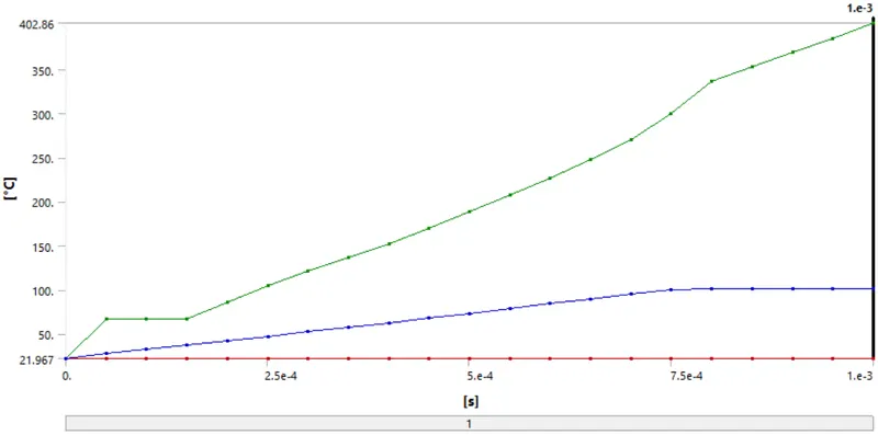
3. Temperature All:
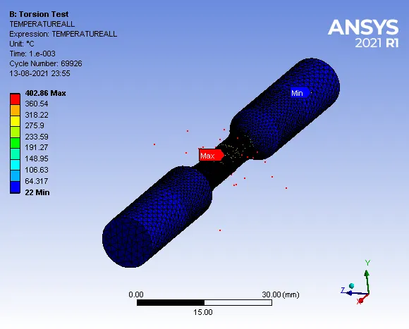
Maximum Temperature = 402.86 °C
- Temperature Contours:
(B) Torsion Test:
1. Total Deformation:
Maximum Deformation = 16.711 mm
- Deformation Contours:
2. Equivalent Stress:
Maximum stress = 595.92 MPa
- Stress Contours:
3. Temperature All:
Maximum Temperature = 402.86 °C
- Temperature Contours:
CONCLUSION:
1. The simulation of the tensile and torsion test was carried out successfully by following the given boundary conditions.
2. From the tensile test results, it was observed that, as the specimen was displaced to 18 mm, the cross-section of the gauge length region starts to decrease, leading to necking. The v-m stress in the necking region was maximum i.e., 477.68 MPa. The temperature of the specimen around the necking region also was increased to 342.35 oC.
3. From the torsion test results, it was observed that, as the specimen was twisted through an angle of 1200 degrees, the gauge length region starts to shear, leading to fracture. The v-m stress in the gauge length region was maximum i.e.,595 .92 MPa. The temperature of the specimen around the necking region also was increased to 402.86 oC.