Week- 5 - Solid meshing
AIM: The Rearview mirror component should mesh by using tetra volume mesh and clear the kinks and dips
OBJECTIVE: The component is to be mesh in both 2D and 3D after checking for any geometrical errors and fixing them and clean up the failing surfaces for minimum element size and should be mesh by ortho tria or tria.
QUALITY CRITERIA
SHELL ELEMENTS
|
S.No |
Quality Criteria |
Value |
|
1 |
Target/Average length |
1 |
|
2 |
Minimum Length |
0.5 |
|
3 |
Maximum Length |
2 |
SOLID ELEMENTS
Use tetra elements to mesh the Volumes defined in the model and check for the below quality after Volume meshing.
|
S.No |
Quality Criteria |
Value |
|
1 |
Tet collapse |
0.2 |
CAD MODEL IMAGE
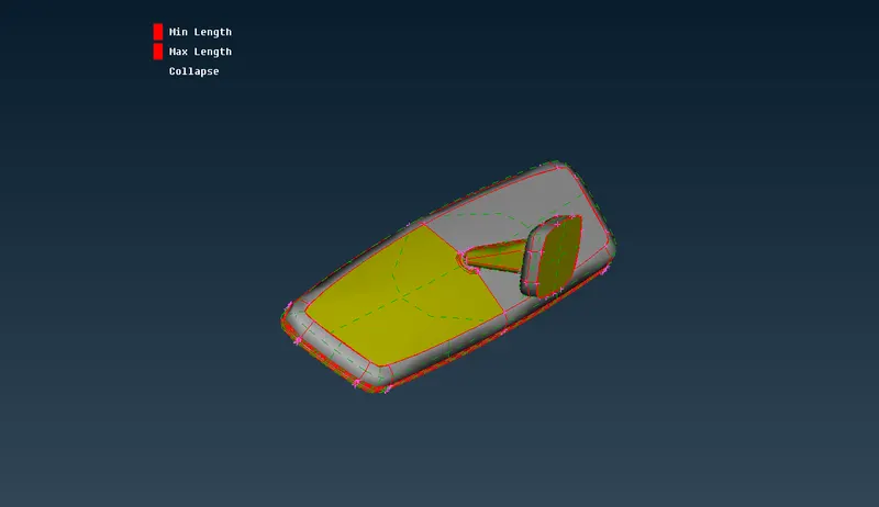
Fig.1 Rearview Mirror
PROCEDURE
1. First open the cad model in ANSA. Give topo to the model to take care of all single cons and to ensure that there are no free edges or any unchecked faces. It can be accessed via FACES>TOPO>SELECT GEOMETRY>MIDDLE CLICK FOR CONFIRMATION
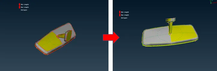
Fig.2 Topo Operation
2.After that as we move forward for meshing before we carry out any operation, we need to carry out a geometry check.
It can be accessed via CHECKS>GEOMETRY.
After detection errors, we can select all the errors and try to fix them automatically via right-click> fix to fix them.
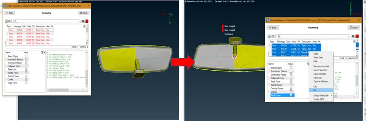
Fig.3 Geometry clean up
3. After that orient the model, using the FACES>ORIENT tool.
Now, After orientation the model we can move toward the meshing before that we need to assign the mesh properties and mesh quality parameter. We need to assign the length parameters. It can be accessed via Goto mesh module>perimeters>length>enter value as per quality criteria mentioned>ok
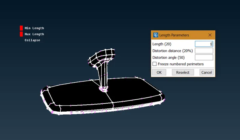
Fig.4 Length Parameters
4. Now, Assign quality parameters and mesh parameters. this is done by accessing parameters from the top toolbar. Enter the values accordingly.
Mesh Parameter
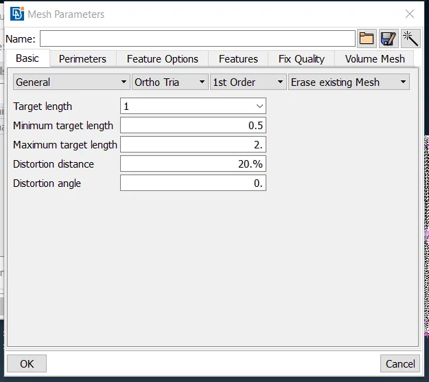
Fig.5 Mesh Parameter
Quality Parameter
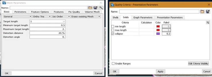
Fig.6 Quality parameters
5. Now we can go for meshing. as comparing the meshing part by auto or manual, I have tried to mesh this component with an auto mesh which is called batch mesh.
Before batch mesh, we need to set some parameters. First checking with the property assigned properly and in batch meshing, we need to set quality and meshing parameters but for this, we need to proceed with either Tria or ortho tria for this component, we go with ortho tria element.
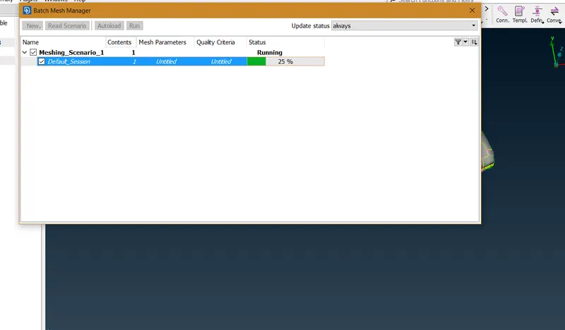
Fig.7 batch mesh
6. Batch mesh completed, the meh flow is good which will give you satisfactory volume mesh.
In batch meshing, we faced some issues like feature line which is not up to minimum length is removed automatically.
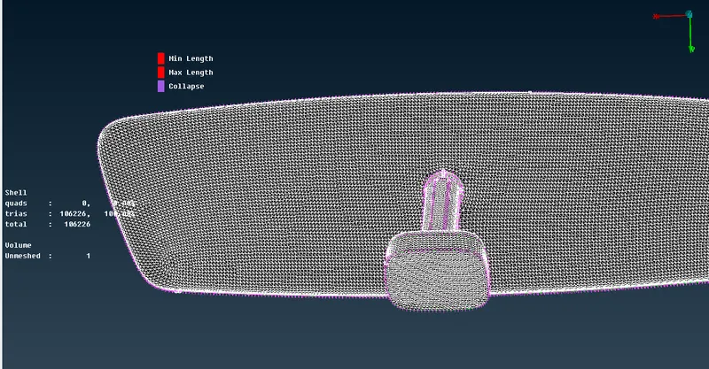
Fig.8 Batch mesh output
7. Now We moved toward the manual mesh, the component has four-part we start meshing from the base part.
The curved surface of any part should be covered with ortho tria mesh to get a good mesh flow and the feature is also covered nicely. For regions that are flat and not as complicated, the tria mesh can be used.
8. We mesh the component with the help of spot mesh. It can be accessed via Mesh generation>Spot mesh. The option is available at the right bottom to change the mesh type, switch mesh type as per convenience and get a good mesh flow.
Use reconstruct option for proper mesh flow and the smooth option to smoothen the mesh to get a good mesh flow
The same process is followed for other parts and deployed with proper mesh flow.
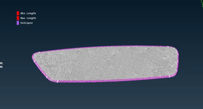
Fig.9 Spot Mesh Base part (Tria and ortho tria)
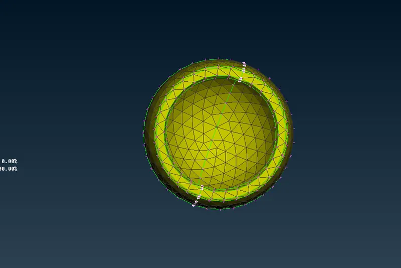
Fig.10 Ball Spot Mesh
10. After deploying 2D shell Mesh on the component, now obtain volume mesh on the component go-to volume mesh module and define a volume. This is done by using Volumes>Define>Manual and then select the component, after selection it's just a matter of middle-clicking for the software to recognize the volume.
After this go to the List menu where you find a defined volume of component There should be $ volumes as shown
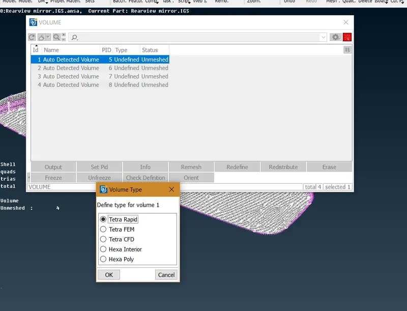
Fig.11 Deploying volume mesh
As the component has different parts they have to defined to have the volume mesh flow properly. Right-click on any volume PID and select volume mesh type then ok, now you got solid mesh throughout the volume of the component.
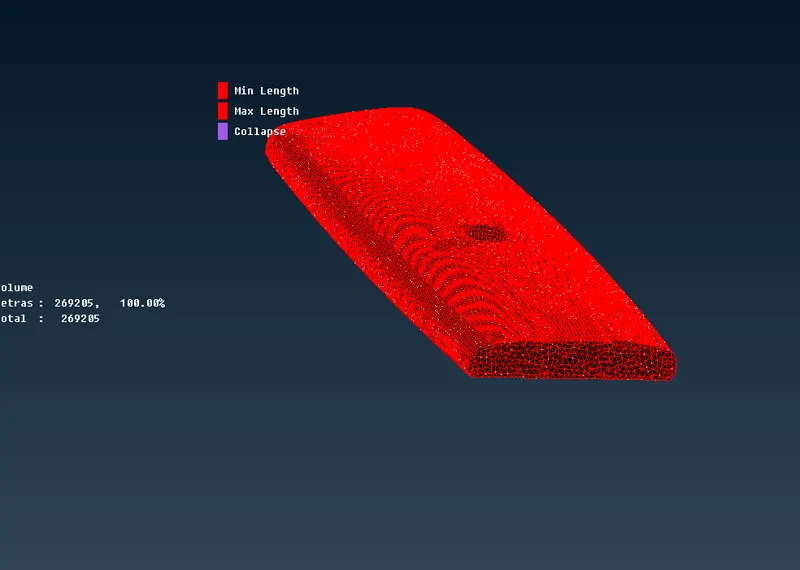
Fig.12 Joint Top plate tetra mesh
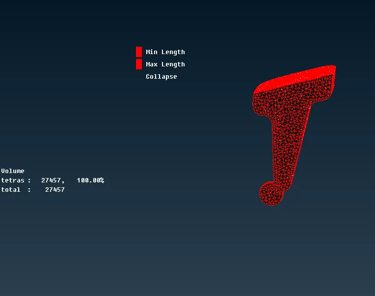
Fig.13 Tetra mesh on top
11. Next, we need to check the solid elements to see if any fail for the tet collapse criteria. If any quality fails to occur we can fix this from the volume mesh module via VOLUME>FIX QUALITY. This is an option that works on failing elements but sometimes we got protrusions on the surface. To avoid this, we have a second option to fix these error, use MV free tool to move the grid in that manner there is no kinks and dips on the surface.
After getting volume mesh on the component, check for kinks and dips on the surface which is fixed manually by aligning them.
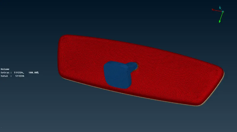 Fig.14 With shadow mode
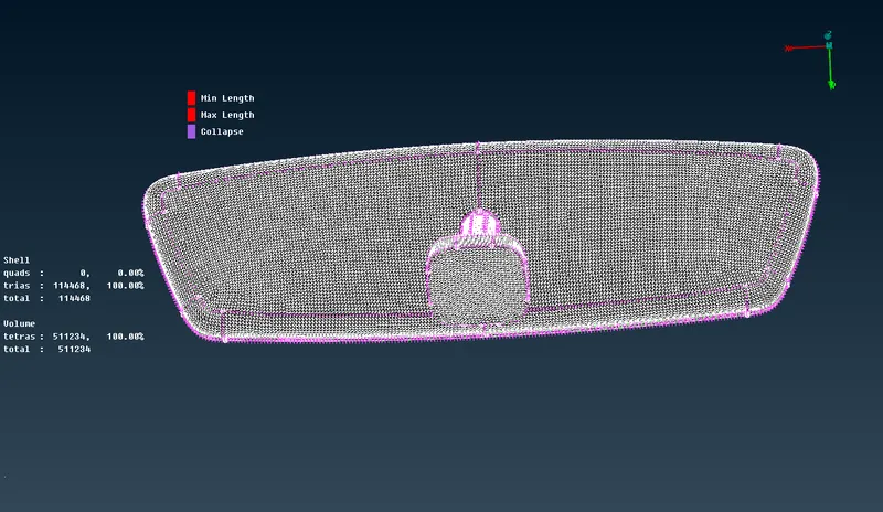
Fig.15 With Hidden Mode
LEARNING OUTCOMES
1. Learnt some tools of solid meshing
2. Learnt to assign volumes for the closed shell.
3. Learnt to fix an error that occurred while meshing.
RESULT
The given model was geometrically fixed and deployed with volume mesh and spot in shell elements with tria and ortho tria and we get a proper and good mesh flow.
CONCLUSION
The challenge is to understand the volume meshing use different options and getting good mesh flow with no off elements no yet collapse.