Week 9 Tension and Torsion test challenge
Tension and Torsion Test
OBJECTIVE:-
1. To perform the tension and torsion test on the specimen provided.
- For the tension test, displace one end of the specimen to 18mm while keeping the other fixed.
- For the torsion test, displace one end of the specimen to an angle of 1200 degree.
2. To find out the total deformation, equivalent stress and temperature of the specimen.
PROCEDURE:-
We can start the simulation by setting up the model. Both the cases are very similar as only the loading condition at the end will change.
1) Defining Material:-
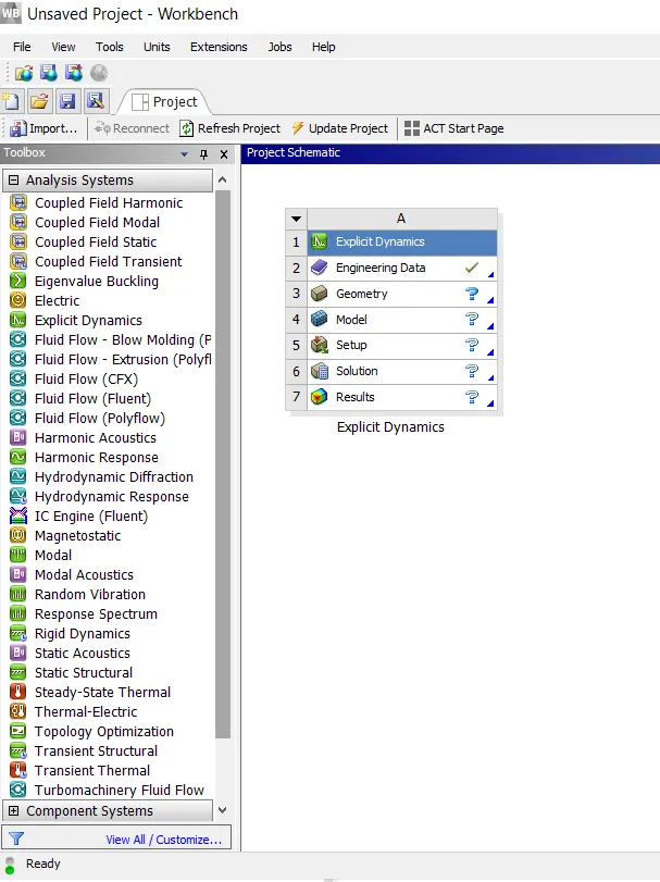
Open the explicit dynamics module into the ansys workbench which can be achieved by simple drag and drop. The material given for the Workpiece will be Steel 1006 which will be under the Explicit material database in the Engineering data Source of Workbench.
2) Importing the Model:-
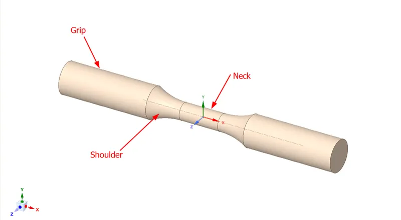
Import the model and open it in SpaceClaim to check for any defects or abnormalities in the geometry.
3) Assigning the Material:-
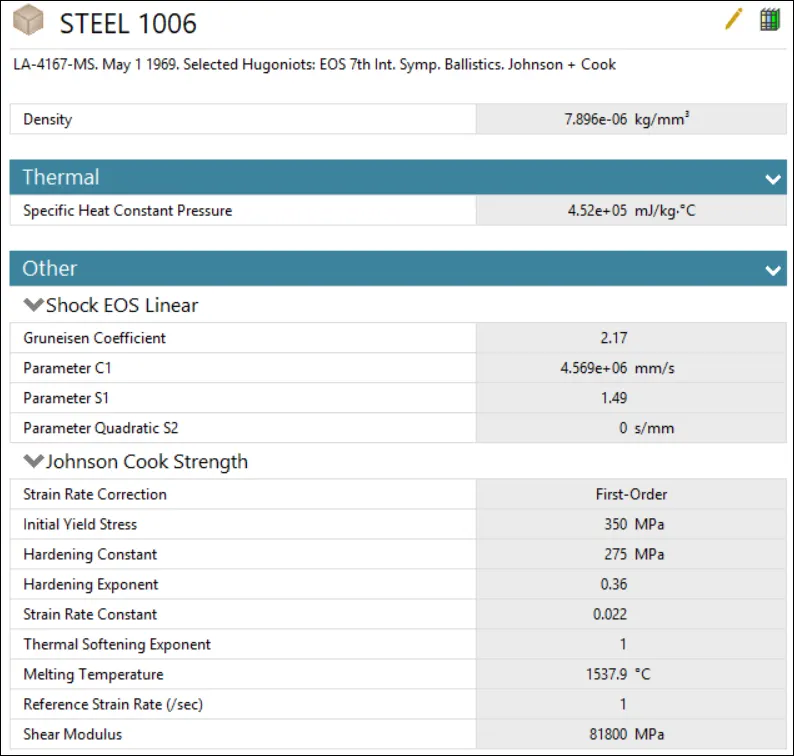
Now assign the Steel 1006 material to the model.
4) Meshing:-
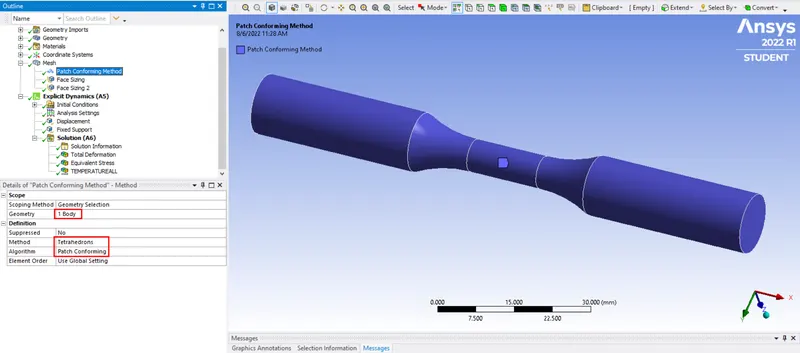
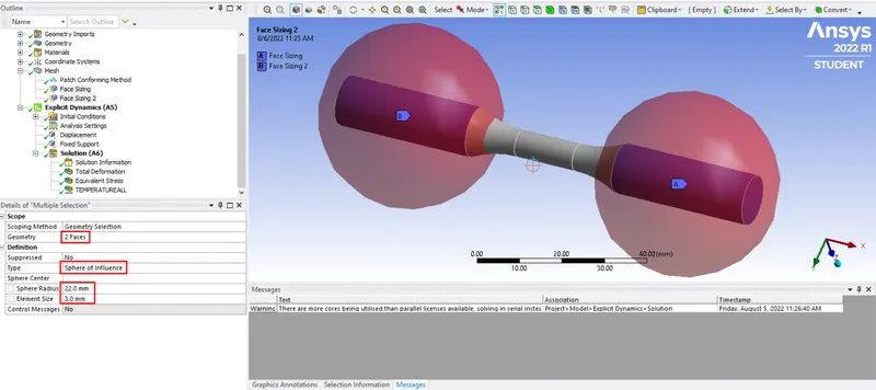
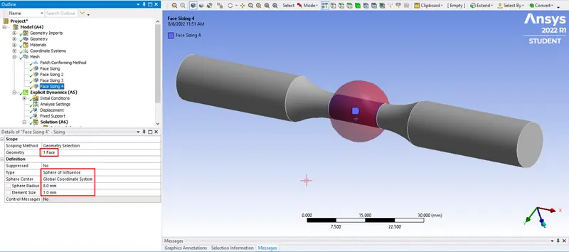
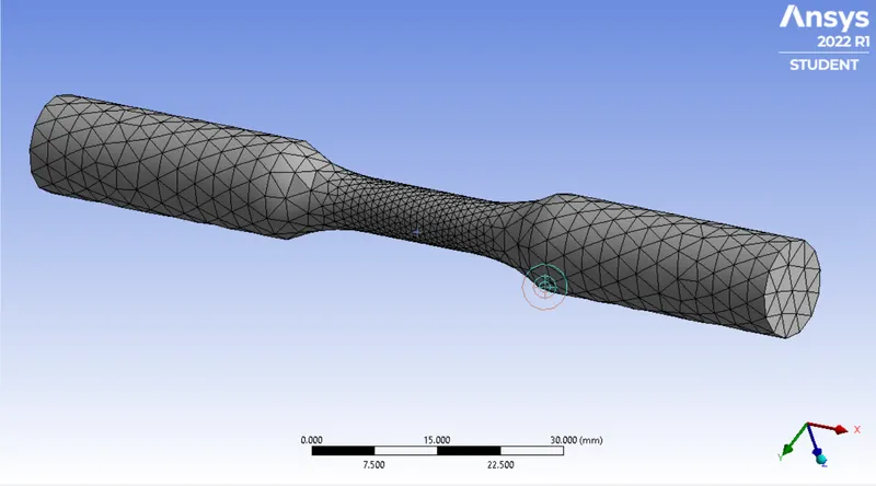
Create 2 local coordinate systems on the both grip faces so that these faces can be meshed with sphere of influence definition. In the meshing step, the specimen was meshed with tetrahedron elements using the patch conforming method. The different sections of the specimen was meshed with the help of sphere of influence. The grip and shoulder section, neck had an element size of 3mm, 1.5mm and 1mm respectively with face sizing option.
5) Analysis Settings:-
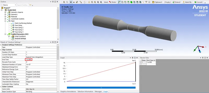
The analysis was carried out in a single step, with the end time step as 0.001.
6) Boundary Conditions:-
Fixed Support - The other grip section is kept completely fixed.
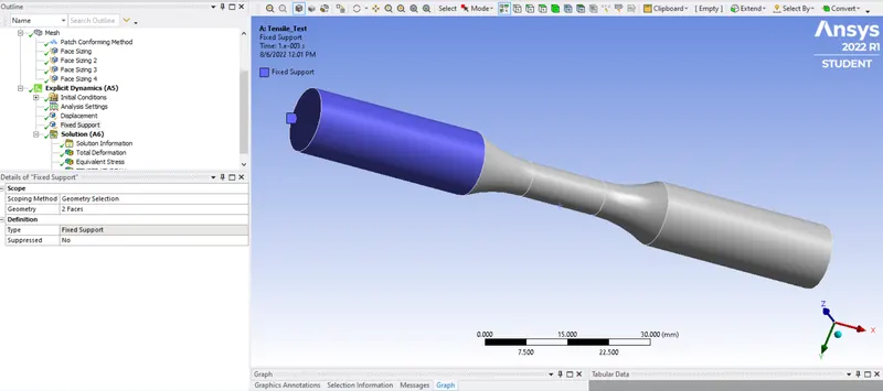
For Tensile Test :
Displacement - Displacement of total 18 mm is given to the grip section of one side of the speciman in X direction using Cartesian Global Coordinate System.
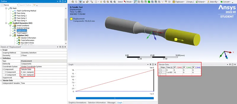
For Torsion Test :
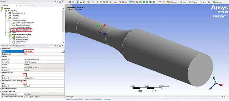
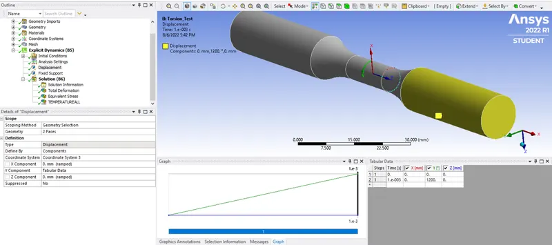
Displacement - Define a Cylindrical Global Coordinate System as shown below. Rotational displacement of 1200 degree in given to the grip section of one side of the speciman in Y direction of rotation using Cylindrical Global Coordinate System.
7) Solution Output:-
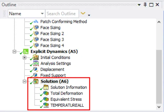
Total deformation, equivalent stress and temperature of the specimen are the parameters that requested as a result for the simulation.
RESULTS:-
1) Tensile Test :
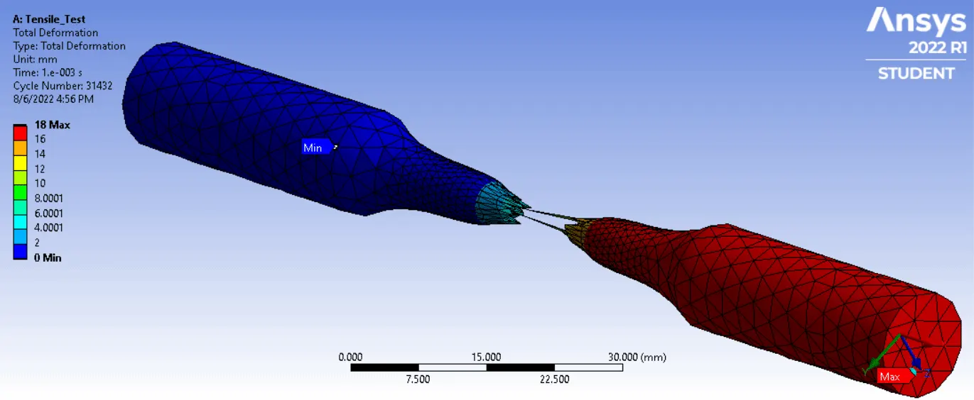
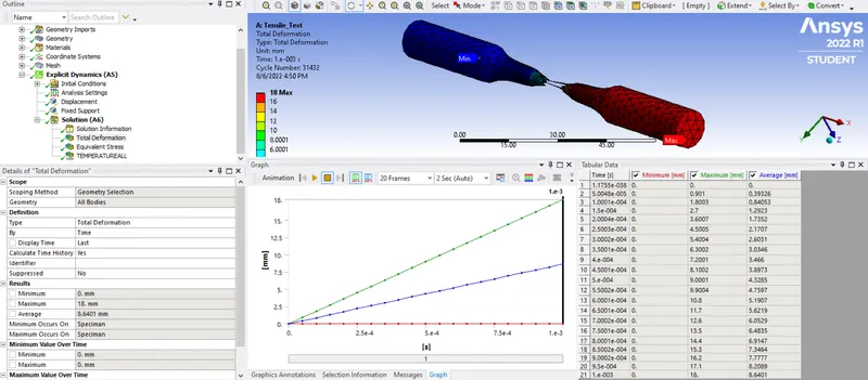
Total Deformation -
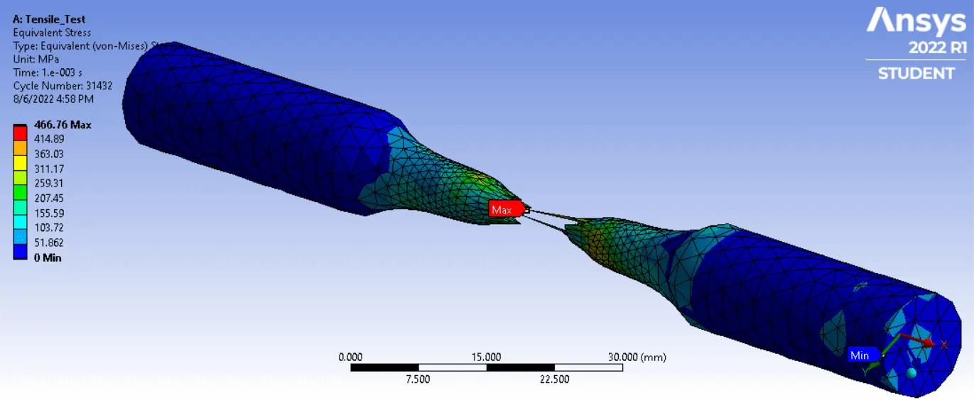
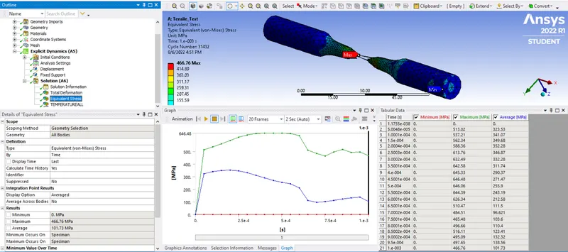
Equivalent Stress -
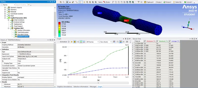
Temperature -
2) Torsion Test :
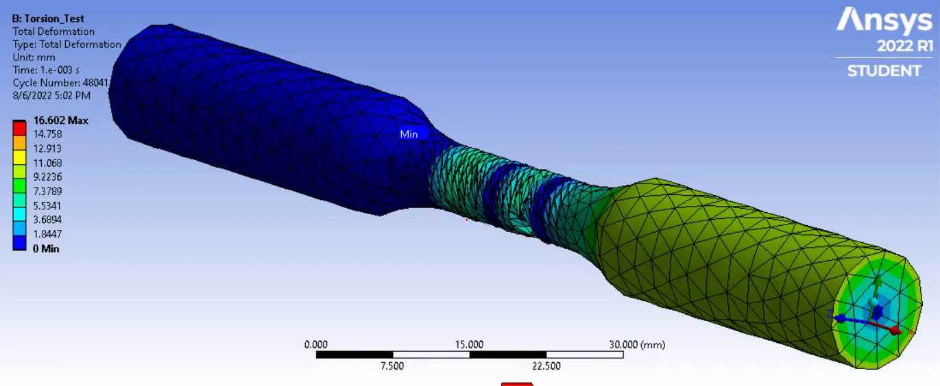
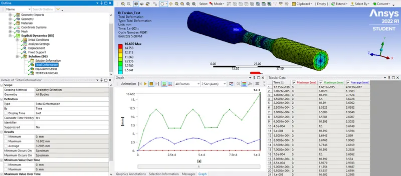
Total Deformation -
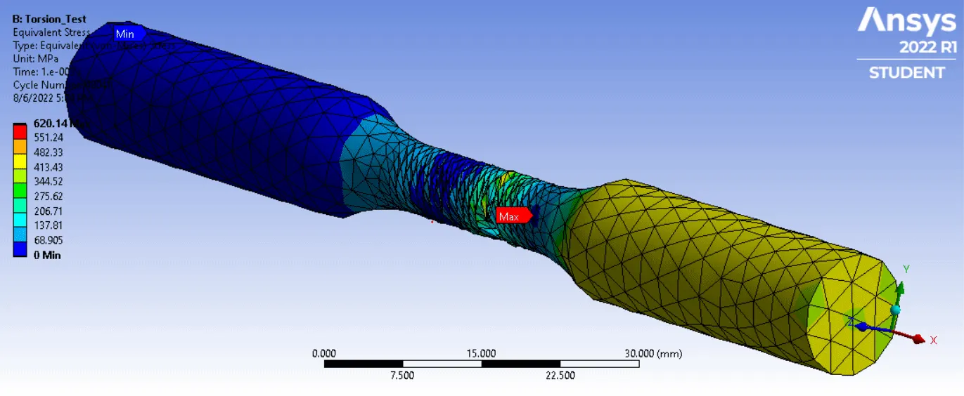
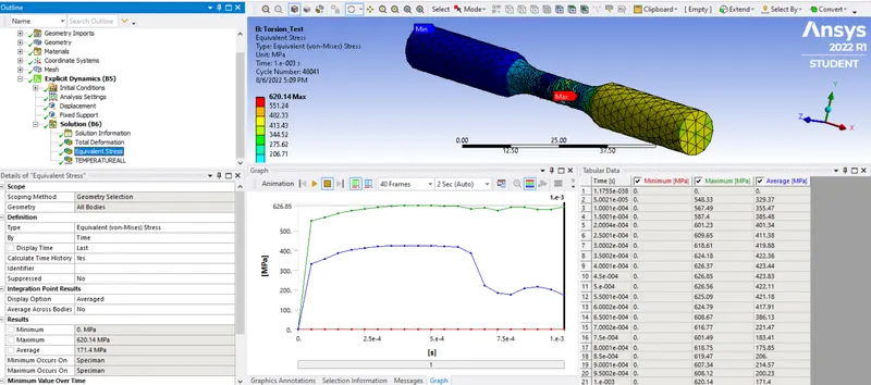
Equivalent Stress -
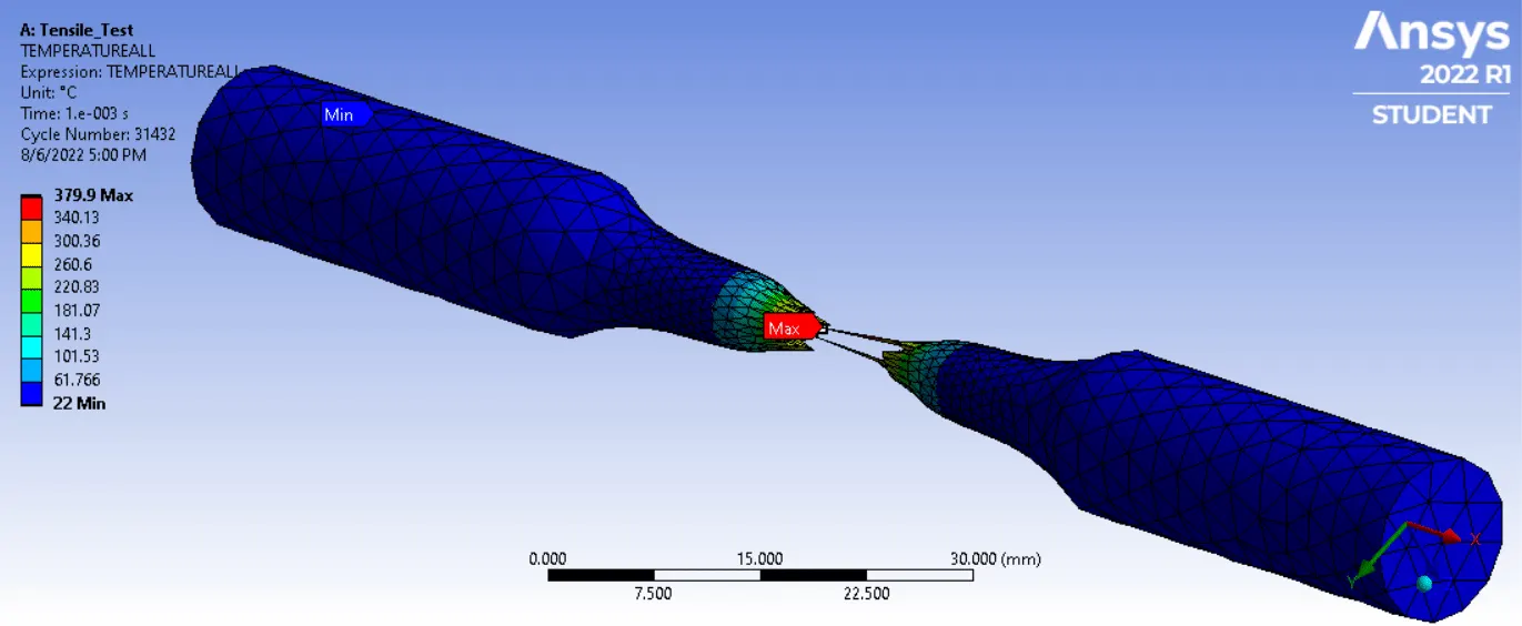
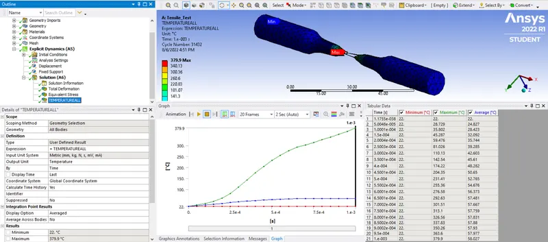
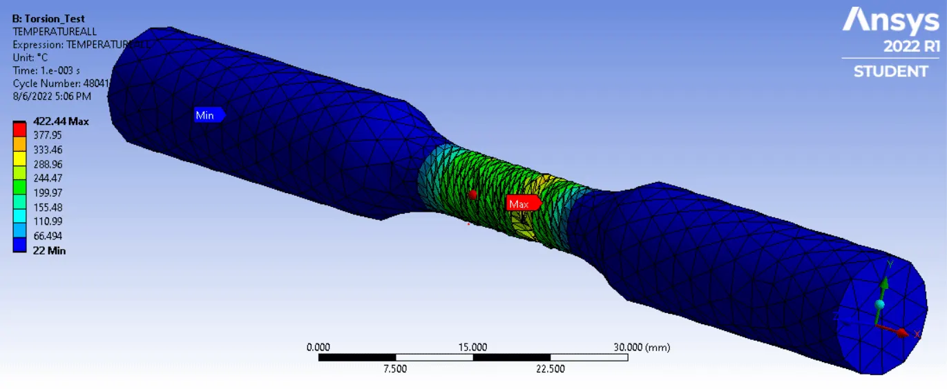
Temperature -
COMPARISION:-
| Cases | Max. Total Deformation | Max. Equivalent Stress | Max. Temperature |
| Tensile Test | 18 mm | 646.48 MPa | 379.9 °C |
| Torsion Test | 16.602 mm | 626.85 MPa | 422.44 °C |
CONCLUSION:-
- The simulation of tensile and torsion test was carried out successfully by following to the given boundary conditions.
- From the tensile test results, it was observed that, as the specimen was displaced to 18 mm, the cross section of the neck region starts to decrease, leading to necking and his concludes that failure of the specimen is due to max. tensile stress. The v-m stress in necking region was maximum 646.48 MPa. The temperature of the specimen around necking region also was increased to 379.9 o C.
- From the torsion test results, it was observed that, as the specimen was twisted through an angle of 1200 degree, the neck region starts to shear, leading to fracture due to max. shear stress. The v-m stress in the neck region was maximum 626.85 MPa. The temperature of the specimen around necking region also was increased to 422.44 o C.